Pipe-bending machine for machining

A pipe bender and sliding rod technology, which is applied in the field of pipe benders for processing, can solve the problems of large manpower consumption, time delay, unfavorable use, etc., and achieve the effects of saving time, easy operation, and easy movement

Inactive Publication Date: 2018-08-17
ZHENGZHOU YUNQI IND EQUIP TECH CO LTD
View PDF0 Cites 0 Cited by
  • Summary
  • Abstract
  • Description
  • Claims
  • Application Information

AI Technical Summary

Problems solved by technology

[0003] At present, most of the existing pipe benders are fixed and not easy to move. When the pipe bender needs to be moved, it takes a lot of manpower, which is very troublesome, time-consuming, and not conducive to people's use. With the advancement of science and technology , With the progress of society, people have put forward higher requirements for pipe benders, so we have proposed a pipe bender for processing to solve the above problems

Method used


Image

  • Pipe-bending machine for machining
  • Pipe-bending machine for machining
  • Pipe-bending machine for machining

Examples


Embodiment Construction

[0021] The following will clearly and completely describe the technical solutions in the embodiments of the present invention with reference to the accompanying drawings in the embodiments of the present invention. Obviously, the described embodiments are only some, not all, embodiments of the present invention.

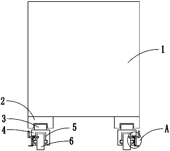
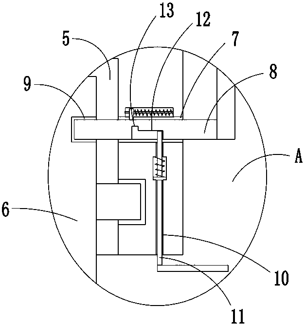
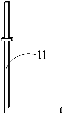
[0022] refer to Figure 1-3 , a pipe bending machine for processing, including a body 1, two fixed blocks 2 are welded on the bottom of the body 1, a rotating shaft 3 is installed on the bottom of the fixed block 2, and a wheel block 4 is welded on the bottom of the rotating shaft 3, and the wheel block The bottom of 4 is provided with a wheel groove 5; the wheel 6 is rotatably installed in the wheel groove 5, and the bottom of the wheel 6 extends to the outside of the wheel groove 5, and the inner walls of the two wheel grooves 5 are provided with slide bar through holes on the side away from each other. 7. A slide bar 8 is slidably installed in the slide bar throug...


PUM


Abstract

The invention discloses a pipe-bending machine for machining. The pipe-bending machine for machining comprises a body, two fixing blocks are welded to the bottom of the body, rotating shafts are rotatably installed at the bottoms of the fixing blocks, wheel blocks are welded to the bottoms of the rotating shafts, wheel slots are formed in the bottoms of the wheel blocks, wheels are rotatably installed in the wheel slots, and the bottoms of the wheels extend outside the wheel slots. Sliding rod through holes are formed in the side walls, away from each other, of the sides of the two wheel slots, sliding rods are installed in the sliding rod through holes in a sliding mode, two ends of the sliding rods extend outside the sliding rod through holes, fixing slots are formed on the sides, closeto the sliding rod through holes, of the wheels, and the ends, close to the wheels, of the sliding rods are connected with fixing slots in a sliding mode. Locating rod through holes are formed in theinner walls of the bottom sides of the sliding rod through holes, and locating rods are installed in the locating rod through holes in a sliding mode. The pipe-bending machine for machining is simplein structure and convenient to use, the body is convenient to move, the operation is easy, the time is saved, and the use of the people is facilitated.

Description

technical field [0001] The invention relates to the technical field of pipe bending machines, in particular to a pipe bending machine used for processing. Background technique [0002] Pipe bending machines are roughly divided into CNC pipe bending machines, hydraulic pipe bending machines, etc., which are used in pipeline laying and repairing in power construction, highway and railway construction, bridges, ships, etc. [0003] At present, most of the existing pipe benders are fixedly placed and are not easy to move. When the pipe bender needs to be moved, it needs a lot of manpower, which is very troublesome, time-consuming, and not conducive to people's use. With the advancement of science and technology , With the progress of society, people have put forward higher requirements for pipe benders, so we have proposed a pipe bender for processing to solve the above problems. Contents of the invention [0004] The object of the present invention is to solve the shortcomin...

Claims


Application Information

Patent Timeline
Patent Type & Authority Applications(China)
IPC IPC(8): B21D7/00
CPCB21D7/00
Inventor 刘国强
Owner ZHENGZHOU YUNQI IND EQUIP TECH CO LTD
Why Eureka
Try Eureka