Metal sheet pulse current auxiliary micro punching device and method

A pulse current, metal sheet technology, applied in metal processing equipment, perforation tools, manufacturing tools, etc., can solve the problems of many hole edge defects, short mold life, large forming force of micro-punching process, etc., to improve production efficiency , The effect of high production efficiency and fast heating speed

Active Publication Date: 2018-08-17
HARBIN INST OF TECH
View PDF8 Cites 10 Cited by
  • Summary
  • Abstract
  • Description
  • Claims
  • Application Information

AI Technical Summary

Problems solved by technology

[0005] The present invention aims to solve the problems of large forming force, short service life of the mold and many defects on the edge of the hole in the existing micro-punching process, and further provides a pulse current-assisted micro-punching device and method for metal sheets

Method used


Image

  • Metal sheet pulse current auxiliary micro punching device and method
  • Metal sheet pulse current auxiliary micro punching device and method
  • Metal sheet pulse current auxiliary micro punching device and method

Examples


specific Embodiment approach 1

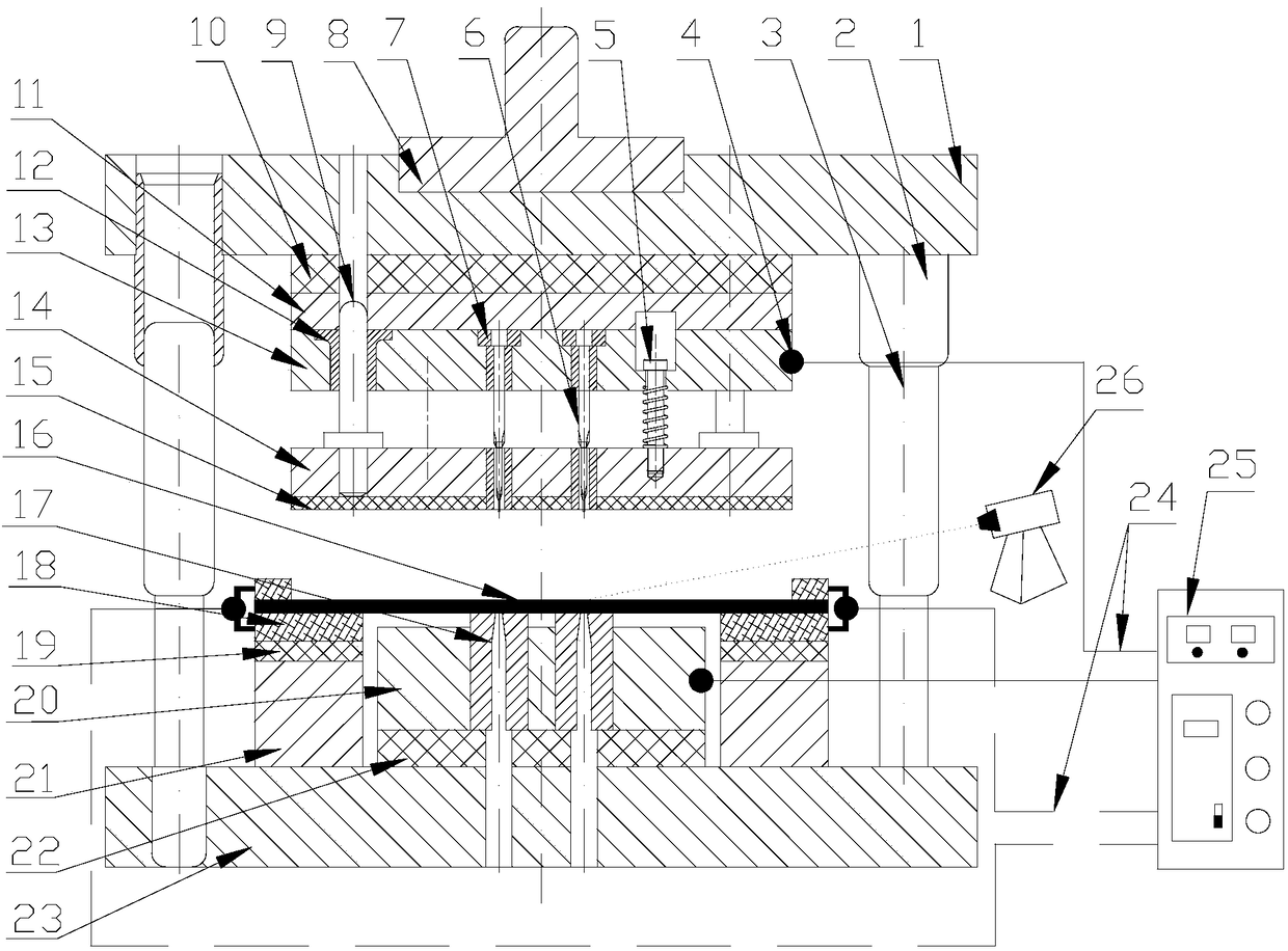
[0034] Specific implementation mode one: combine figure 1 and figure 2 To illustrate this embodiment, a pulse current assisted micro-punching device for a thin metal plate includes a mold assembly and a pulse power supply system; Plate 10, upper backing plate 11, punch fixing plate 13, punch 6, support plate 14, heat insulation plate 15, die 17, die fixing plate 20, lower insulating plate 22 and lower template 23, upper template 1, The upper insulating plate 10, the upper backing plate 11 and the punch fixing plate 13 are connected as one, the die fixing plate 20, the lower insulating plate 22 and the lower template 23 are connected as one, the support plate 14 and the heat insulating plate 15 are connected as one, and the upper A spring 5 is also installed between the backing plate 11, the punch fixing plate 13 and the supporting plate 14, the die 17 is arranged in the die fixing plate 20, and the upper template 1 and the lower template 23 are arranged on the guide sleeve 1...

specific Embodiment approach 2

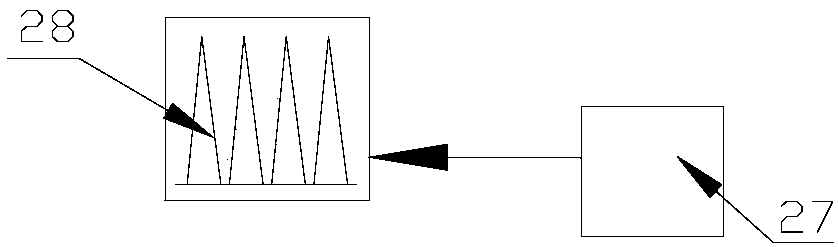
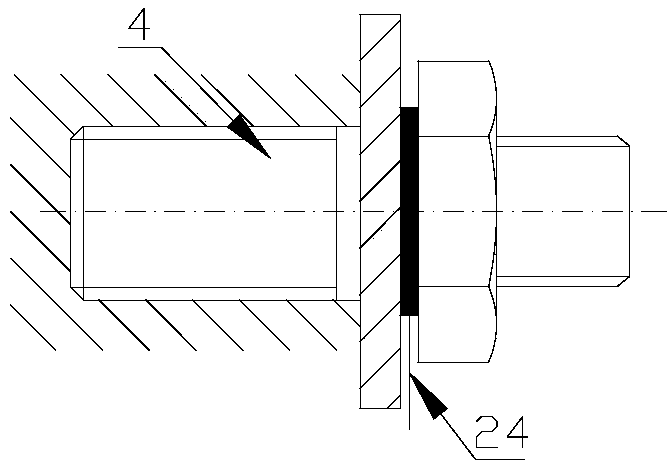
[0036] Specific implementation mode two: combination Figure 1 to Figure 3 Illustrate this embodiment, the pulse power supply system of this embodiment provides the way of energizing the loop heating blank as follows: the pulse power supply system includes a pulse current generator 28, a power lead 24, an electrode contact device 4 and a pulse current controller 27; the pulse current generator The output terminal of 28 is connected with the electrode contact device 4 on the punch fixed plate 13 and the die fixed plate 20 through the power lead 24, and the input terminal of the pulse current generator 28 is connected with the output end of the pulse current controller 27, and the pulse current The controller 27 sends the programmed pulse current parameter signal to the pulse current generator 28, and the pulse current generator 28 outputs a corresponding pulse current according to the received pulse current control signal, and the pulse current passes through the punch fixing pl...

specific Embodiment approach 3

[0039] Specific implementation mode three: combination Figure 1 to Figure 3 Describe this embodiment, the mode that the pulse power supply system of this embodiment provides energization loop heating billet is: pulse power supply system comprises pulse current generator 28, power lead wire 24, electrode contact device 4 and pulse current controller 27; Die assembly also comprises Two sets of clamping insulation assemblies, each set of clamping insulation assemblies include a blank clamping electrode 18, an insulating gasket 19 and a spacer 21 arranged from top to bottom and connected as a whole; the spacer 21 is installed on the lower insulating plate 22, and the blank 16 is installed on the blank holding electrode 18; the output end of the pulse current generator 28 is connected with the electrode contact device 4 on the two blank holding electrodes 18 through the power lead 24, and the input end of the pulse current generator 28 is connected with the pulse current The outpu...


PUM

PropertyMeasurementUnit
thicknessaaaaaaaaaa
strengthaaaaaaaaaa

Abstract

The invention discloses a metal sheet pulse current auxiliary micro punching device and method, and relates to a micro punching device and method so as to solve the problems an existing micro punchingtechnology is great in shaping force, a mould service life is short and hole edge defects are multiple. The metal sheet pulse current auxiliary micro punching device comprises a mould assembly and apulse power source system; the mould assembly comprises a die shank, an upper die plate, an upper insulating plate, an upper backing plate, a punch head fixing plate, a punch head, a supporting plate,a heat insulating plate, a female die, a female die fixing plate, a lower insulating plate and a lower die plate which are arranged from top to bottom sequentially; and the female die is arranged inthe female die fixing plate. The metal sheet pulse current auxiliary micro punching method comprises the steps that one, installation and debugging are carried out; two, technological parameters are selected; three blank loading is carried out; four, blank micro punching forming is carried out; and five, micropore piece demoulding is carried out. The metal sheet pulse current auxiliary micro punching device and the metal sheet pulse current auxiliary micro punching method are suitable for micro punching forming on materials, like a titanium alloy, a nickel base alloy and high-strength steel, which are difficult to form or can not be formed by a conventional micro punching method.

Description

technical field [0001] The invention relates to a micro-punching device and method, in particular to a pulse-current-assisted micro-punching device and method for a thin metal plate, and belongs to the technical fields of mechanical manufacturing and plastic micro-forming. Background technique [0002] Microporous thin plate parts are widely used in various fuel injection (steam) nozzles, microelectronic integrated circuits, aerospace electronics, lead frames, etc. The size of microporous parts or their characteristic dimensions are less than or equal to 1mm in at least two directions. The precision requirement is very high. However, the micro-hole processing technology based on ion etching, laser and micro-EDM generally has problems such as low efficiency, poor precision, and long processing cycle. For microporous parts with a pore diameter of 0.05 to 1 mm, micro-punching technology will replace the existing cold processing process to obtain microporous parts with good per...

Claims


Application Information

Patent Timeline
Patent Type & Authority Applications(China)
IPC IPC(8): B21D28/34B21D28/26B21D37/16
CPCB21D28/26B21D28/34B21D37/16
Inventor 徐杰郭斌单德彬包建兴
Owner HARBIN INST OF TECH
Why Eureka
Try Eureka