Auxiliary jig for transferring cylindrical mold standard parts

A standard and cylindrical technology, which is applied in the field of auxiliary fixtures for transferring cylindrical mold standard parts, can solve the problems of high labor intensity, low work efficiency, and heavy workload.

Inactive Publication Date: 2018-08-17
DONGGUAN LIANZHOU INTPROP OPERATION MANAGEMENT CO LTD
View PDF11 Cites 0 Cited by
  • Summary
  • Abstract
  • Description
  • Claims
  • Application Information

AI Technical Summary

Problems solved by technology

After the mold standard parts are processed, they need to be stacked in batches in the corresponding storage box. The existing stacking method generally adopts manual blanking and manual stacking, while the manual stacking needs to stack the mold standard parts one by one. Put it in the box, and some mold standard parts need to be stacked in the box, so the workload is heavy, and the labor intensity for the staff is relatively high, and the work efficiency is not high

Method used


Image

  • Auxiliary jig for transferring cylindrical mold standard parts
  • Auxiliary jig for transferring cylindrical mold standard parts
  • Auxiliary jig for transferring cylindrical mold standard parts

Examples


Embodiment Construction

[0021] The specific implementation manners of the present invention will be further described in detail below in conjunction with the accompanying drawings and embodiments. The following examples are used to illustrate the present invention, but are not intended to limit the scope of the present invention.

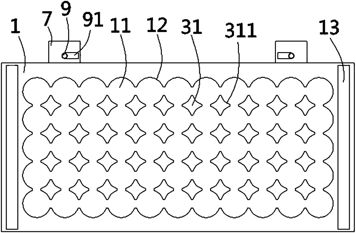
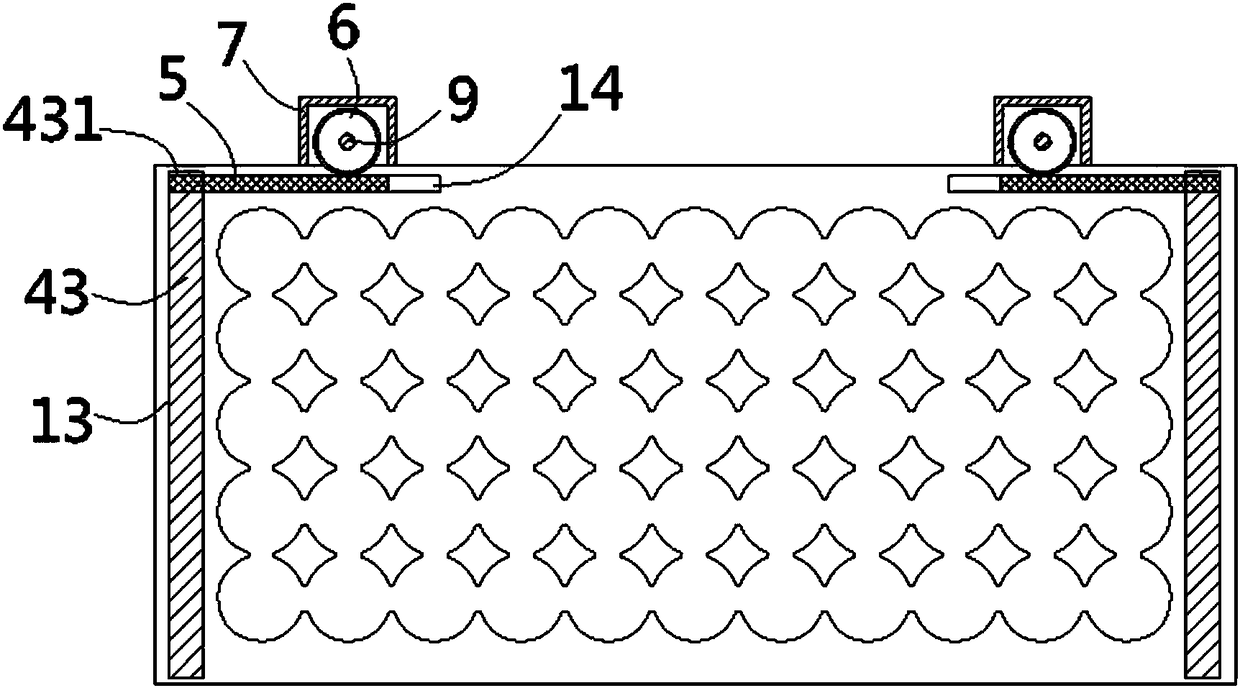
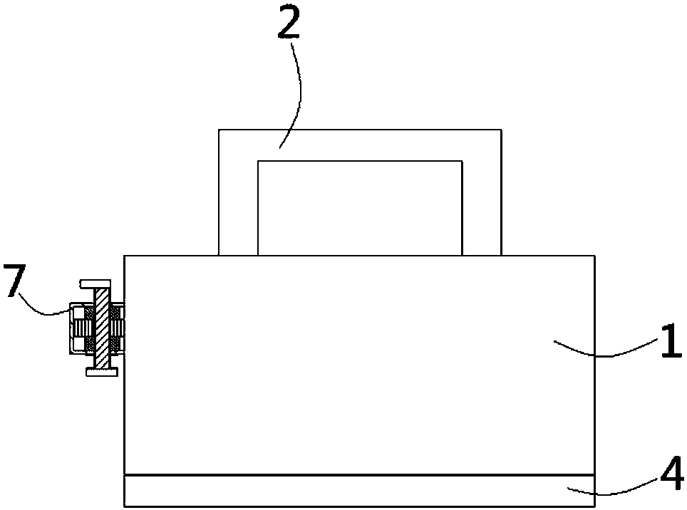
[0022] see figure 1 , image 3 , Figure 5 According to the present invention, an auxiliary jig for transferring cylindrical mold standard parts includes a rectangular box body 1, two handles 2 are fixed on the upper end surface of the box body 1, and the lower end surface of the box body 1 There is a placement groove 11 formed on the top, and a plurality of arc grooves 12 matching with the mold standard parts are formed on the inner wall of the placement groove 11. The arc grooves 12 are connected end to end, and the placement groove 11 is provided with a plurality of Distributed prism-shaped partition columns 31, the lower end surface of the box body 1 leans against t...


PUM


Abstract

The invention discloses an auxiliary jig for transferring cylindrical mold standard parts. The auxiliary jig comprises a rectangular box body, a placement groove is formed in the lower end surface ofthe box body, a plurality of partition columns are arranged in the placement groove, a partition plate abuts against the lower end surface of the box body, a sinking table is formed on the upper end surface of the partition plate, and the bottom surface of the sinking table is provided with prismatic partition blocks corresponding to the partition columns; limiting plates are formed on the parts,on the two sides of the sinking table, of the upper end surface of the separation plate, the limiting plates are inserted into inserting grooves, and limiting holes are formed in one ends of the limiting plates; and connecting grooves communicating with the inserting grooves are formed in the parts, on one sides of the placement grooves, of the box body, a rack is inserted into each connecting groove, a gear is connected with each rack in a meshed mode, the gears penetrate out of the side wall of the box body and are arranged in cover shells fixed to the side wall of the box body, a spline hole is formed in the center of each gear, a spline shaft is inserted into each spline hole, and the lower ends of the spline shafts penetrate out of the cover shells to form positioning discs. Accordingto the auxiliary jig, stacking operation of the mold standard parts can be realized conveniently, and the mold standard parts can be conveniently stored in the box.

Description

Technical field: [0001] The invention relates to the technical field of mold standard part processing equipment, in particular to an auxiliary jig for transferring cylindrical mold standard parts. Background technique: [0002] Mold standard parts are needed in the use of molds, such as standard punches, positioning pins, springs, etc. After the mold standard parts are processed, they need to be stacked in batches in the corresponding storage box. The existing stacking method generally adopts manual blanking and manual stacking, while the manual stacking needs to stack the mold standard parts one by one. Put it into the box, and some mold standard parts need to be stacked in the box, so its workload is large, and the labor intensity of the staff is relatively large, and the work efficiency is not high. [0003] In view of the above-mentioned defects, the designer actively researches and innovates, in order to create a new type of auxiliary fixture for transferring cylindric...

Claims


Application Information

Patent Timeline
Patent Type & Authority Applications(China)
IPC IPC(8): B65B35/50B65B61/22B65B5/10
CPCB65B5/10B65B35/50B65B61/22
Inventor 徐亚维
Owner DONGGUAN LIANZHOU INTPROP OPERATION MANAGEMENT CO LTD
Why Eureka
Try Eureka