
Remote-transmission LED illumination lamp

A lighting and remote transmission technology, which is applied in outdoor lighting, lighting devices, fixed lighting devices, etc., can solve the problem that it is difficult to judge cars and road equipment, tunnels and related equipment, and can not play the role of light brightness and identification, light brightness detector Problems such as inability to illuminate, achieve good light brightness and long-distance effect, good light brightness and long-distance effect, and improve the effect of brightness and remote transmission

Pending Publication Date: 2018-08-17
周晓东
View PDF0 Cites 0 Cited by
  • Summary
  • Abstract
  • Description
  • Claims
  • Application Information

AI Technical Summary

Problems solved by technology

Existing road equipment, tunnels and related equipment night light brightness and cleanliness devices mainly use reflectors and reflective tubes, relying on reflecting the light emitted by vehicles to play the role of light brightness.
[0003] This kind of light brightness and distance effect not only depends on the lighting of the car, if there is no lighting of the car, it will not play the role of light brightness and recognition, but also due to the influence of the ambient background light, when the light source is weak, the incident light The reflected light intensity is also weak and cannot play the role of light brightness and identification. It is also difficult for traffic participants to judge the distance between the car and road equipment, tunnels and related equipment based on the light brightness and distance, especially when the light is not good When it is used, it will cause psychological barriers to traffic participants and easily cause traffic accidents

Method used


Image

  • Remote-transmission LED illumination lamp
  • Remote-transmission LED illumination lamp
  • Remote-transmission LED illumination lamp

Examples


Embodiment 1

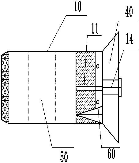
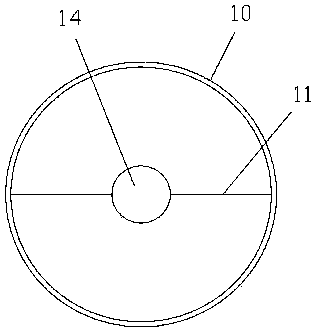
[0025] As shown in Figures 1 and 2, according to an embodiment of the present invention, a LED remote lighting lamp is provided, including a light box 10, a spotlight remote transmission device 50, and a light-emitting LED diode 60, wherein the light box 10 is used for setting in a tunnel On the traffic lighting facilities, the structure of the light box is designed to install the light-concentrating remote transmission device and the light-emitting LED diode device in the light box according to specific structural composition and positional relationship. Built into the light box 10 respectively, the concentrating remote transmission device 50 is used to collect and transmit the light in the light-emitting LED diode 60. The light-emitting LED diode device 60 is also provided with a fluorescent layer at the middle position, which is conducive to heat dissipation, adjustment and absorption LED light stores the light energy after being irradiated by natural light and ultraviolet l...

Embodiment 2

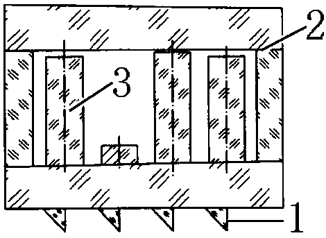
[0034] like figure 1 , figure 2 , image 3, on the basis of Example 1, according to this article, the structure and implementation of the concentrating remote transmission device 50 will be described in detail. In the LED remote transmission lighting provided by the present invention, the concentrating remote transmission device 50 is arranged in the light box 10. In the middle cavity, it is used to collect and strengthen the incident light and then emit the illumination. Its structure is as follows image 3 , comprising four mirror columns 1, an optical path channel 2, four sloped prism mirrors 3, and a light concentrator, the four mirror columns 1 all have oblique mirror surfaces, and the four mirror columns 1 are installed in the optical path channel In the upper part, the optical path channel 2 is provided with four slope prisms 3, and the four slope prisms 3 are the first slope prism and the second slope prism from left to right. , the third slope prism mirror, the fou...

Embodiment 3

[0037] like figure 1 , figure 2 , image 3 and Figure 4 ,, on the basis of Example 1, according to this article, the structure of the concentrating remote transmission device 50 and another embodiment are described in detail. In the LED remote transmission lighting provided by the present invention, the focusing The optical remote transmission device 50 includes 6 edges 1, an optical path channel 2, 6 sloped prism mirrors 3, and a light concentrator. The 6 mirror columns 1 all have oblique mirror surfaces, and the 6 mirror columns 1 are installed In the upper part of the optical path channel, the optical path channel 2 is provided with 6 slope prism mirrors 3, and the 6 wedge-shaped prismatic square 3 columns are successively the first slope prism mirror, the second one from left to right. The slope prism mirror, the third slope prism mirror, the fourth slope prism mirror, the fifth slope prism mirror, and the wedge-angle mirror columns correspond to the incident light ba...


PUM


Abstract

The invention relates to an LED illumination device in the field of illumination facilities. The LED illumination device specifically comprises a lamp box, a condensation and remote transmission device and an LED device, wherein the lamp box has a space and a size suitable for mounting illumination elements; the condensation and remote transmission device is arranged in a middle cavity of the lampbox and used for condensing and enhancing incident light and then emitting light for illumination, and the condensation and remote transmission device can emit non-dispersed light after condensing and enhancing the incident light; the LED device is arranged in the lamp box, is adjacent to the condensation and remote transmission device to provide an incident light source for the condensation andremote transmission device, and is used for providing a light source and the incident light; and meanwhile, the structural design of the lamp box meets the requirement for mounting the condensation and remote transmission device and the LED device in the lamp box according to specific structural compositions and positional relations. The LED illumination device is reasonable in design, compact instructure, easy to mount, capable of improving the brightness and the remote-transmission effect and high in adaptability and has wide application prospects in tunnel traffic and night traffic illumination and night operation of equipment.

Description

technical field [0001] The invention relates to the field of lighting equipment, in particular to an LED lighting device. Background technique [0002] In the current road traffic, damage to tunnels and night guardrails, as well as failures of road equipment and tunnels and related traffic road facilities, etc. are mostly scratched by vehicles or insufficient lighting brightness and distance are the main reasons for accidents. These accidents basically occur At night, therefore, night lighting for road equipment and tunnels and related equipment is one of the fundamental ways to reduce accidents. Existing night light brightness and cleanliness devices for road equipment, tunnels and related equipment mainly adopt reflectors and reflector tubes, relying on the light emitted by reflecting vehicles to play the role of light brightness devices that cannot be illuminated or even identified. [0003] Such light brightness and distance effects not only depend on the lighting of th...

Claims


Application Information

Patent Timeline
Patent Type & Authority Applications(China)
IPC IPC(8): F21S8/00F21V5/00F21V5/02F21V19/00F21W131/101F21Y115/10
CPCF21S8/00F21V5/008F21V5/02F21V19/001F21W2131/101F21Y2115/10
Inventor 周晓东侯振凯刘芳高建成
Owner 周晓东
Learn More