
Lane line-based vehicle positioning method and application thereof

A vehicle positioning and lane line technology, applied in the vehicle field, can solve the problems of insufficient accuracy and real-time performance, high precision requirements, etc., and achieve the effect of solving the overall positioning problem

Active Publication Date: 2018-08-17
UISEE TECH BEIJING LTD
View PDF7 Cites 24 Cited by
  • Summary
  • Abstract
  • Description
  • Claims
  • Application Information

AI Technical Summary

Problems solved by technology

[0002] Intelligent driving, such as ADAS (Advanced Intelligent Driving Assistance) and unmanned driving, especially unmanned driving, has high requirements for location accuracy because it involves personal and vehicle safety. The accuracy and real-time performance of the conventional positioning methods currently used are remarkable insufficient

Method used


Image

  • Lane line-based vehicle positioning method and application thereof
  • Lane line-based vehicle positioning method and application thereof
  • Lane line-based vehicle positioning method and application thereof

Examples


Embodiment Construction

[0045] The following description serves to disclose the invention to enable those skilled in the art to carry out the invention. The preferred embodiments described below are only examples, and those skilled in the art can devise other obvious variations. The basic principles of the present invention defined in the following description can be applied to other embodiments, variations, improvements, equivalents and other technical solutions without departing from the spirit and scope of the present invention.

[0046] The terms and words used in the following description and claims are not limited to the bibliographical meanings, but, are merely used by the inventor to enable a clear and consistent understanding of the invention. Accordingly, it will be apparent to those skilled in the art that the following descriptions of various embodiments of the present invention are provided for illustration purpose only and not for the purpose of limiting the invention as defined by the ...


PUM


Abstract

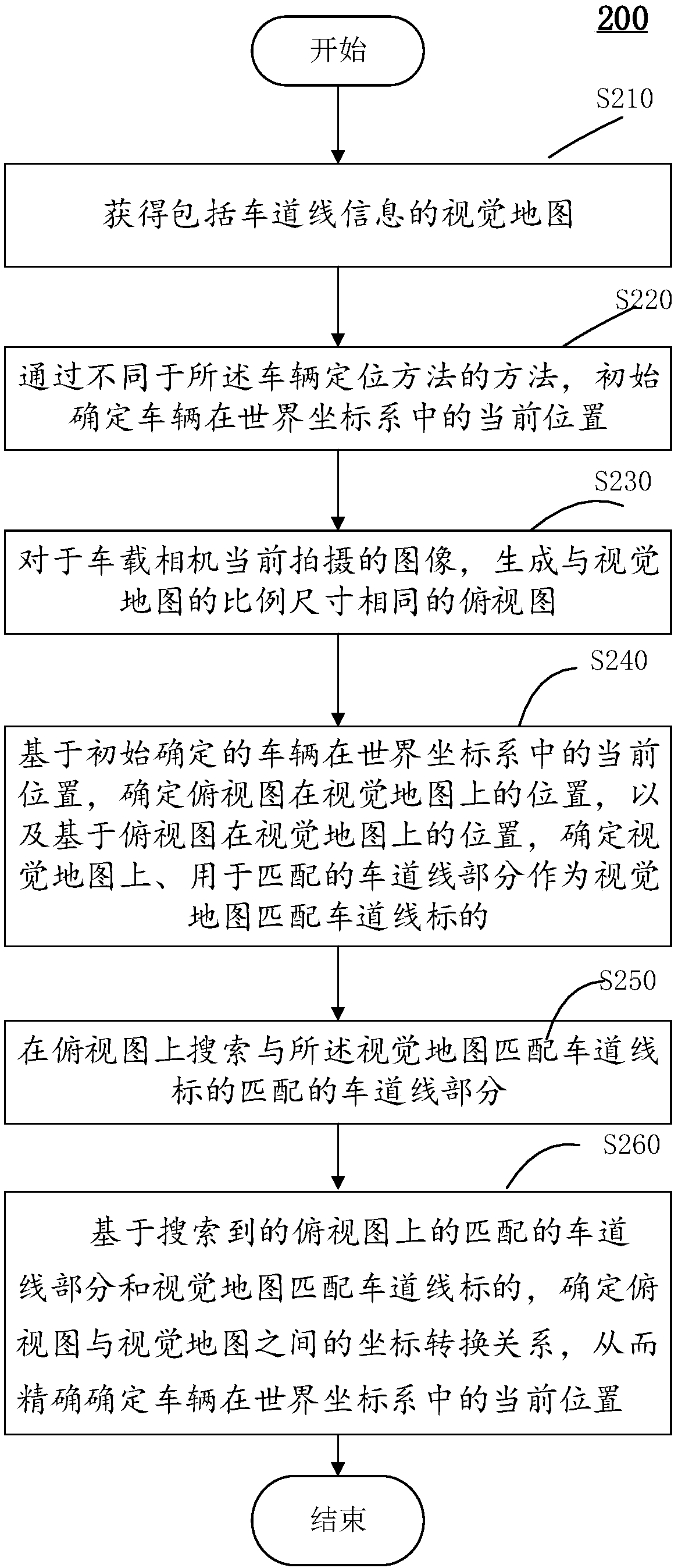
The invention provides a lane line-based vehicle positioning method, a calculating device, an intelligent vehicle, and a surface mark-based vehicle positioning method are provided. The lane line-basedvehicle positioning method includes the following steps: obtaining a visual map including lane line information; initially determining the current position of a vehicle in a world coordinate system;generating a top view having the same proportion and dimension with the visual map based on an image currently captured by a vehicle camera; determining the position of the top view on the visual mapbased on the initially determined current position of the vehicle, and determining a lane line part on the visual map, used for matching, as a visual map matching lane line mark based on the positionof the top view on the visual map; searching a lane line part matched with the visual map matching lane line mark on the top view; and determining a coordinate transformation relationship between thetop view and the visual map based on the matching lane line part on the top view and the visual map matching lane line mark in order to accurately determine the current position of the vehicle in theworld coordinate system.

Description

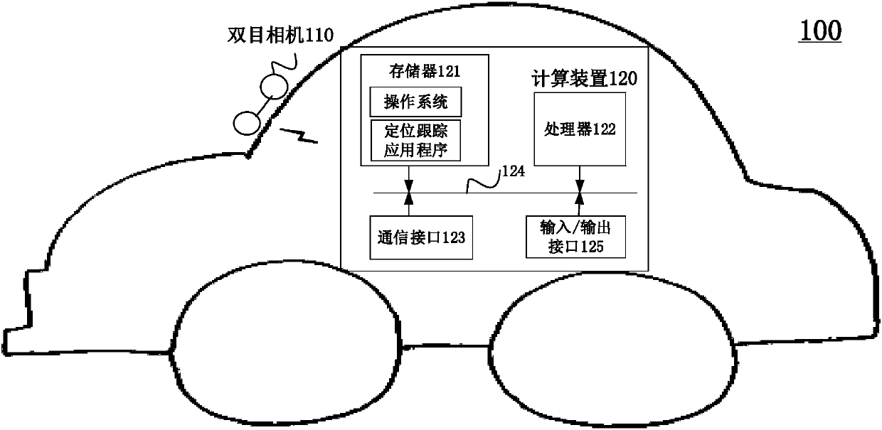
technical field [0001] The present invention generally relates to computer vision-based vehicle positioning technology, and in particular to a vehicle positioning method, computing device, computer storage medium and vehicle based on landmark information and visual maps on the ground. Background technique [0002] Intelligent driving, such as ADAS (Advanced Intelligent Driving Assistance) and unmanned driving, especially unmanned driving, has high requirements for position accuracy due to the safety of people and vehicles. The accuracy and real-time performance of the conventional positioning methods currently used are remarkable. insufficient. Contents of the invention [0003] The present invention has been made in view of the above circumstances. [0004] According to one aspect of the present invention, a vehicle positioning method based on lane lines is provided, which may include: obtaining a visual map including lane line information; initially determining that the...

Claims


Application Information

Patent Timeline
IPC IPC(8): G01C21/30G01C11/00
CPCG01C11/00G01C21/30
Inventor 王雪梅
Owner UISEE TECH BEIJING LTD
Learn More