Microfluid fuel cell with right trapezoid-shaped porous electrodes

A porous electrode and right-angled trapezoidal technology, applied in fuel cells, circuits, electrical components, etc., can solve the problems of increasing the overall size of the battery, adverse effects of microfluidic fuel cells, and unbalanced flow field distribution, and achieve a balanced flow field distribution Effect

Inactive Publication Date: 2018-08-17
JIANGSU UNIV OF TECH
View PDF2 Cites 3 Cited by
  • Summary
  • Abstract
  • Description
  • Claims
  • Application Information

AI Technical Summary

Problems solved by technology

[0002] Microfluidic fuel cells use the laminar flow characteristics of microflow to naturally stratify fuel and oxide fluids without the use of proton exchange membranes. They are simple in structure and low in cost, and have great application potential in portable electronic devices. Among the microfluidic fuel cells, the microfluidic fuel cells with porous electrodes show good performance advantages. In these microfluidic fuel cells with porous electrodes, the porous electrodes are generally rectangular, and the electrode extension ends are clamped by extending the electrode length. The separator is fixed in the battery in the slot. However, relevant studies have found that the flow field distribution in these rectangular porous electrodes is not balanced, and the flow velocity near the outlet side is relatively high, and the fixing method of extending the electrode length increases the battery life. Overall size, which adversely affects the application of microfluidic fuel cells in portable electronic devices

Method used


Image

  • Microfluid fuel cell with right trapezoid-shaped porous electrodes
  • Microfluid fuel cell with right trapezoid-shaped porous electrodes

Examples


Embodiment Construction

[0019] In order to make the technical solutions of the present invention clearer and clearer to those skilled in the art, the present invention will be further described in detail below in conjunction with the examples and accompanying drawings, but the embodiments of the present invention are not limited thereto.

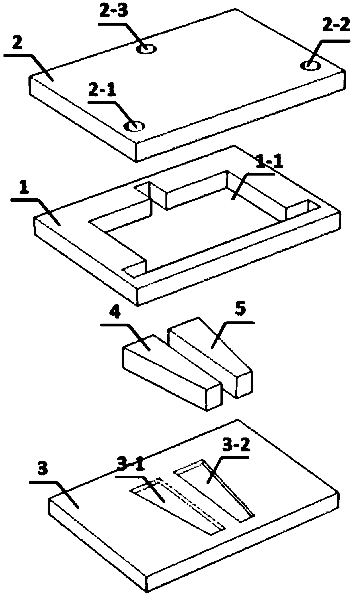
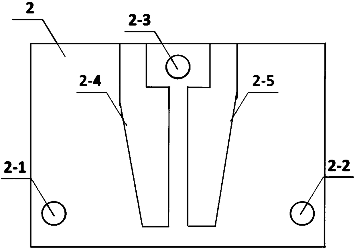
[0020] Such as figure 1 and figure 2 As shown, a microfluidic fuel cell with right-angled trapezoidal porous electrodes provided in this embodiment is made of a separator 1 and an upper cover plate 2 and a lower cover plate 3 covering the upper and lower sides of the separator 1 through heat-compression packaging. , the separator 1 is provided with a fluid channel 1-1, the upper cover 2 is provided with an anolyte inlet 2-1, a catholyte inlet 2-2 and a reaction solution outlet 2-3, the upper cover An anode current collector 2-4 and a cathode current collector 2-5 of a metal layer are deposited on the inner surface of the plate 2, and the anode current collector 2...


PUM

PropertyMeasurementUnit
thicknessaaaaaaaaaa
thicknessaaaaaaaaaa
depthaaaaaaaaaa

Abstract

The invention discloses a microfluid fuel cell with right trapezoid-shaped porous electrodes, which belongs to the technical field of fuel cells. The microfluid fuel cell is made of a diaphragm and anupper cover board and a lower cover board covering the top and bottom of the diaphragm by hot-pressing packaging, the interior of the diaphragm is provided with a fluid flow passage, the upper coverboard is provided with an anolyte inlet, a catholyte inlet, and a reaction fluid outlet, an anode current collector and a cathode current collector which are metal layers are deposited on the internalsurface of the upper cover board, the anode current collector and the cathode current collector are respectively connected to external wires in order to output electric energy generated in the fuel cell to an external circuit load, the bottom of the lower cover board is provided with grooves, and the right trapezoid-shaped porous electrodes are arranged in the grooves. The lower cover board groove design adopted by the invention can prevent the enlargement of cell size while effectively fixing the porous electrodes, and the adopted right trapezoid-shaped electrode design can balance the distribution of flow fields in the porous electrodes.

Description

technical field [0001] The invention relates to a microfluidic fuel cell, in particular to a microfluidic fuel cell with a rectangular trapezoidal porous electrode, and belongs to the technical field of fuel cells. Background technique [0002] Microfluidic fuel cells use the laminar flow characteristics of microflow to naturally stratify fuel and oxide fluids without the use of proton exchange membranes. They are simple in structure and low in cost, and have great application potential in portable electronic devices. Among the microfluidic fuel cells, the microfluidic fuel cells with porous electrodes show good performance advantages. In these microfluidic fuel cells with porous electrodes, the porous electrodes are generally rectangular, and the electrode extension ends are clamped by extending the electrode length. The separator is fixed in the battery in the slot. However, relevant studies have found that the flow field distribution in these rectangular porous electrodes...

Claims


Application Information

Patent Timeline
Patent Type & Authority Applications(China)
IPC IPC(8): H01M8/0258H01M8/0247
CPCH01M8/0247H01M8/0258Y02E60/50
Inventor 巢宇姜柳柳李丽
Owner JIANGSU UNIV OF TECH
Why Eureka
Try Eureka