High Power Linear Electromagnetic Acceleration System
A linear electromagnetic and acceleration system technology, applied in the field of motors, can solve the problems of difficult dynamic current sharing control and no fault tolerance function
- Summary
- Abstract
- Description
- Claims
- Application Information
AI Technical Summary
Problems solved by technology
Method used
Image
Examples
Embodiment 1
[0074] Embodiment one: combine below Figure 3 to Figure 7 This embodiment will be described in detail.
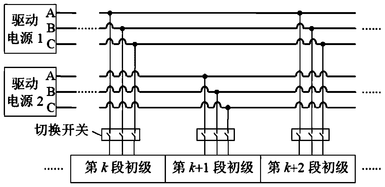
[0075] The high-power linear electromagnetic acceleration system described in this embodiment includes a high-power twelve-phase linear motor and a high-voltage inverter system;
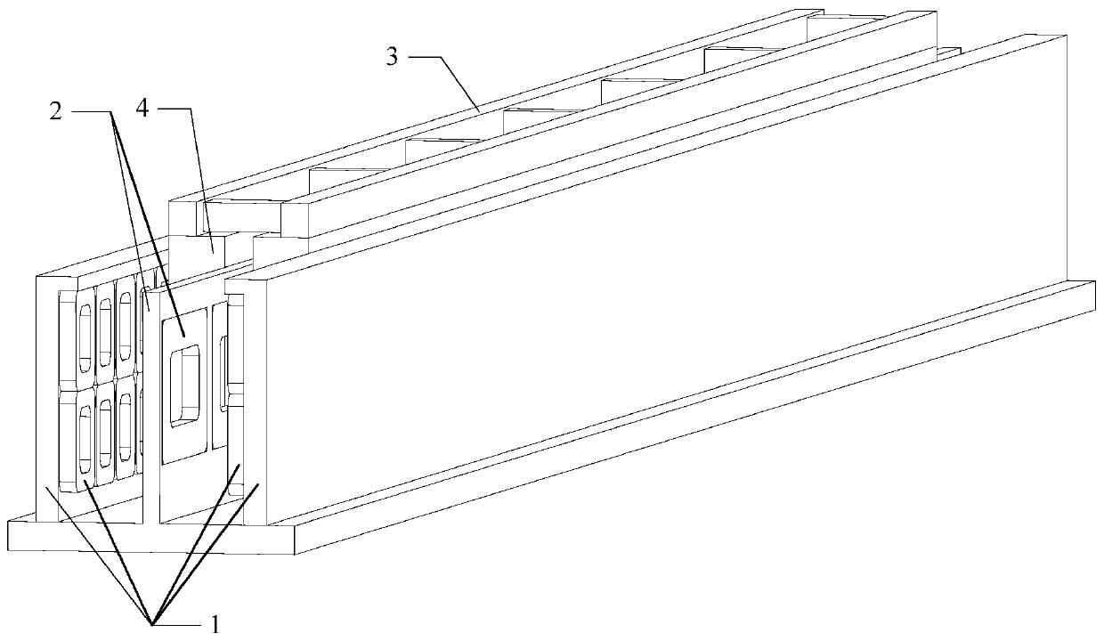
[0076] The high-power twelve-phase linear motor has a long primary and short secondary structure, the primary is a twelve-phase coreless centralized winding, and the secondary is a five-pair pole structure;
[0077] High-power twelve-phase linear motor includes stator and mover;
[0078] The stator is fixed on the ground, the stator includes suspension, guide primary 1 and propulsion primary 2, the mover is installed on the skid car 3, the mover includes a cryogenic container 4 and a superconducting coil 5, and the superconducting coil 5 is fixed in the cryogenic container 4 ;
[0079] Both the levitation and guiding primary 1 are double-sided structures, and each side of the primary includes ...
Embodiment 2
[0083] Embodiment two: combine below Figure 8 and Figure 9 This embodiment will be described in detail.
[0084] The circuit structure of the coil drive unit or the phase coil drive unit of the high-power linear electromagnetic acceleration system described in this embodiment is the same;
[0085] The circuit structure includes a power supply U i0 , Power U i1 , power switching device S 1 , power switching device S 2 , power switching device S 3 , power switching device S 4 , power switching device S 01 , power switching device S 02 , power switching device S 11 and the power switching device S 12 ;
[0086] Power switching device S 1 The negative pole of the power switching device S 2 connected to the positive pole to form a bridge arm;
[0087] Power switching device S 3 The negative pole of the power switching device S 4 The positive pole of the bridge is connected to form another bridge arm;
[0088] Connect the two bridge arms in parallel to form a full...
Embodiment 3
[0095] Embodiment three: the following combination Figure 10 and Figure 11 This embodiment will be described in detail.
[0096] The circuit structure of the coil drive unit or the phase coil drive unit of the high-power linear electromagnetic acceleration system described in this embodiment is the same;
[0097] The circuit structure includes a power supply U i0 , Power U i1 , power switching device S 1 , power switching device S 2 , power switching device S 3 , power switching device S 4 , Diode D 1 and diode D 2 ;
[0098] Power switching device S 1 The positive pole and the power supply U i0 The anode of the power switch S 1 The negative pole of the power switching device S 2 The anode of the power switch S 2 The negative pole of the power switching device S 3 The anode of the power switch S 3 The negative pole of the power switching device S 4 The anode of the power switch S 4 The negative pole of the power supply U i1 connected to the negative pole; ...
PUM
 Abstract
Description
Claims
Application Information
 - R&D
- Intellectual Property
- Life Sciences
- Materials
- Tech Scout
- Unparalleled Data Quality
- Higher Quality Content
- 60% Fewer Hallucinations
Browse by: Latest US Patents, China's latest patents, Technical Efficacy Thesaurus, Application Domain, Technology Topic, Popular Technical Reports.
© 2025 PatSnap. All rights reserved.Legal|Privacy policy|Modern Slavery Act Transparency Statement|Sitemap|About US| Contact US: help@patsnap.com


