High-power linear electromagnetic acceleration system

A linear electromagnetic and acceleration system technology, applied in the field of motors, can solve problems such as lack of fault tolerance and difficulty in dynamic current sharing control

Active Publication Date: 2018-08-17
HARBIN INST OF TECH +1
View PDF2 Cites 2 Cited by
  • Summary
  • Abstract
  • Description
  • Claims
  • Application Information

AI Technical Summary

Problems solved by technology

[0008] The present invention proposes a high-power linear electromagnetic acceleration system in order to solve the problems that the drive system of the existing high-power linear electromagnetic acceleration system is difficult to control the dynamic current and does not have a fault-tolerant function.

Method used


Image

  • High-power linear electromagnetic acceleration system
  • High-power linear electromagnetic acceleration system
  • High-power linear electromagnetic acceleration system

Examples


Embodiment 1

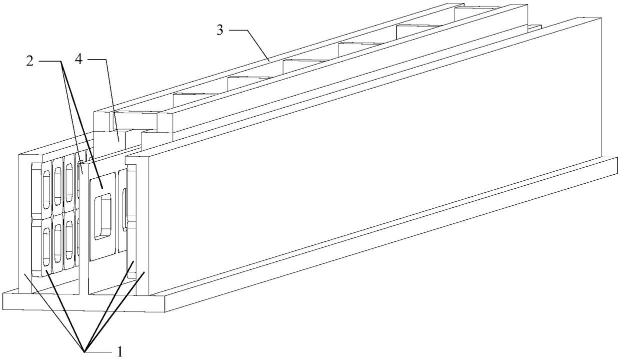
[0074] Embodiment one: combine below Figure 3 to Figure 7 This embodiment will be described in detail.

[0075] The high-power linear electromagnetic acceleration system described in this embodiment includes a high-power twelve-phase linear motor and a high-voltage inverter system;

[0076] The high-power twelve-phase linear motor has a long primary and short secondary structure, the primary is a twelve-phase coreless centralized winding, and the secondary is a five-pair pole structure;

[0077] High-power twelve-phase linear motor includes stator and mover;

[0078] The stator is fixed on the ground, the stator includes suspension, guide primary 1 and propulsion primary 2, the mover is installed on the skid car 3, the mover includes a cryogenic container 4 and a superconducting coil 5, and the superconducting coil 5 is fixed in the cryogenic container 4 ;

[0079] Both the levitation and guiding primary 1 are double-sided structures, and each side of the primary includes ...

Embodiment 2

[0083] Embodiment two: combine below Figure 8 and Figure 9 This embodiment will be described in detail.

[0084] The circuit structure of the coil drive unit or the phase coil drive unit of the high-power linear electromagnetic acceleration system described in this embodiment is the same;

[0085] The circuit structure includes a power supply U i0 , Power U i1 , power switching device S 1 , power switching device S 2 , power switching device S 3 , power switching device S 4 , power switching device S 01 , power switching device S 02 , power switching device S 11 and the power switching device S 12 ;

[0086] Power switching device S 1 The negative pole of the power switching device S 2 connected to the positive pole to form a bridge arm;

[0087] Power switching device S 3 The negative pole of the power switching device S 4 The positive pole of the bridge is connected to form another bridge arm;

[0088] Connect the two bridge arms in parallel to form a full...

Embodiment 3

[0095] Embodiment three: the following combination Figure 10 and Figure 11 This embodiment will be described in detail.

[0096] The circuit structure of the coil drive unit or the phase coil drive unit of the high-power linear electromagnetic acceleration system described in this embodiment is the same;

[0097] The circuit structure includes a power supply U i0 , Power U i1 , power switching device S 1 , power switching device S 2 , power switching device S 3 , power switching device S 4 , Diode D 1 and diode D 2 ;

[0098] Power switching device S 1 The positive pole and the power supply U i0 The anode of the power switch S 1 The negative pole of the power switching device S 2 The anode of the power switch S 2 The negative pole of the power switching device S 3 The anode of the power switch S 3 The negative pole of the power switching device S 4 The anode of the power switch S 4 The negative pole of the power supply U i1 connected to the negative pole; ...


PUM


Abstract

The invention relates to a high-power linear electromagnetic acceleration system and belongs to the field of motors. The driving system of a conventional high-power linear electromagnetic accelerationsystem has a great difficulty in dynamic current-sharing control and does not have a fault-tolerant function. The high-power linear electromagnetic acceleration system is characterized in that coilsin a primary starting region has a large number of series turns, a coil driver has a small output current, a purpose of driving the low-speed section of a linear motor by using a driver with a small current and a high chopping frequency is achieved; coils in a primary terminal region has a small number of series turns and the coil driver has a large output current. When the high-speed section is driven, multiple parallel unit coils are connected in parallel, and each parallel unit coil is driven separately, thereby realizing a purpose of driving a high-power motor in parallel by using small and medium power drivers, avoiding the great difficulty in dynamic current-sharing control caused by parallel connection of multiple power switching devices and achieving the fault tolerance of the driving system.

Description

technical field [0001] The invention relates to an electromagnetic acceleration system and belongs to the field of motors. Background technique [0002] Existing high-power linear electromagnetic acceleration systems are mainly used in carrier-based aircraft of aircraft carriers, electromagnetic ejection of unmanned aerial vehicles and early warning aircraft, auxiliary launch of missiles, booster launch of aerospace vehicles, and high-speed and high-acceleration electromagnetic propulsion test systems and other occasions. Among them, the carrier-based aircraft electromagnetic catapult is a typical high-power linear electromagnetic acceleration system, which is mainly composed of a high-power linear motor, an electric energy storage device and a power converter. The carrier-based aircraft electromagnetic catapult uses the traveling electromagnetic force generated by the high-power linear motor to propel the carrier-based aircraft to take-off speed. It has many advantages such...

Claims


Application Information

Patent Timeline
Patent Type & Authority Applications(China)
IPC IPC(8): H02K41/02H02M7/5387H02M7/483
CPCH02K41/02H02M7/483H02M7/5387
Inventor 寇宝泉韦坚金银锡
Owner HARBIN INST OF TECH
Why Eureka
Try Eureka