
Indoor distribution communication system monitoring device and monitoring method

A communication system and indoor distribution technology, applied in wireless communication, electrical components, etc., can solve problems such as potential safety hazards, affecting normal use, and difficulty in manpower detection, and achieve accurate real-time alarm and positioning, high accuracy, and strong reliability Effect

Pending Publication Date: 2018-08-17
TONGHAO CABLE GRP CO LTD
View PDF0 Cites 4 Cited by
  • Summary
  • Abstract
  • Description
  • Claims
  • Application Information

AI Technical Summary

Problems solved by technology

For indoor coverage, leaky cables, feeders and passive components are mostly distributed in ceilings or cable wells based on the requirements of beautification. After long-term operation, due to equipment aging and other reasons, failures occur from time to time, but the cable well space for indoor coverage Narrow, making fault detection in indoor coverage very difficult
[0003] At present, most of the actual maintenance process of indoor coverage links can only rely on technicians to check in sections, which is time-consuming and labor-intensive, and the cables or devices in the cable shaft and ceiling cannot be located during the inspection, and manual inspection is very difficult. At the same time, due to The cables used in cable wells need to be pulled out from the well for inspection, so the power supply needs to be cut off first, which not only affects normal use, but also poses a great safety hazard
Although there are some indoor coverage link monitoring devices on the market, most of the existing technologies fail to meet the requirements for simultaneous monitoring of multiple indoor distributed links. Even though some monitoring devices can meet the multi-link monitoring requirements, they need to be The end of each link is tested by adding a terminal, the layout is complicated and cumbersome, and the power supply problem of the monitoring device is difficult to solve, and it is difficult to achieve practical application results

Method used


Image

  • Indoor distribution communication system monitoring device and monitoring method
  • Indoor distribution communication system monitoring device and monitoring method
  • Indoor distribution communication system monitoring device and monitoring method

Examples


Embodiment 1

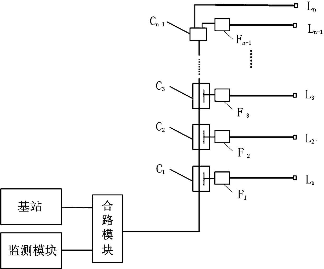
[0054] Such as image 3 shown, the frequency selector F i in series with the coupler C i And the corresponding indoor communication link L i between, the frequency selector F i Screen out the indoor distribution signal S and the indoor distribution communication link L i The monitoring signal S i And send to the corresponding indoor communication link L i .

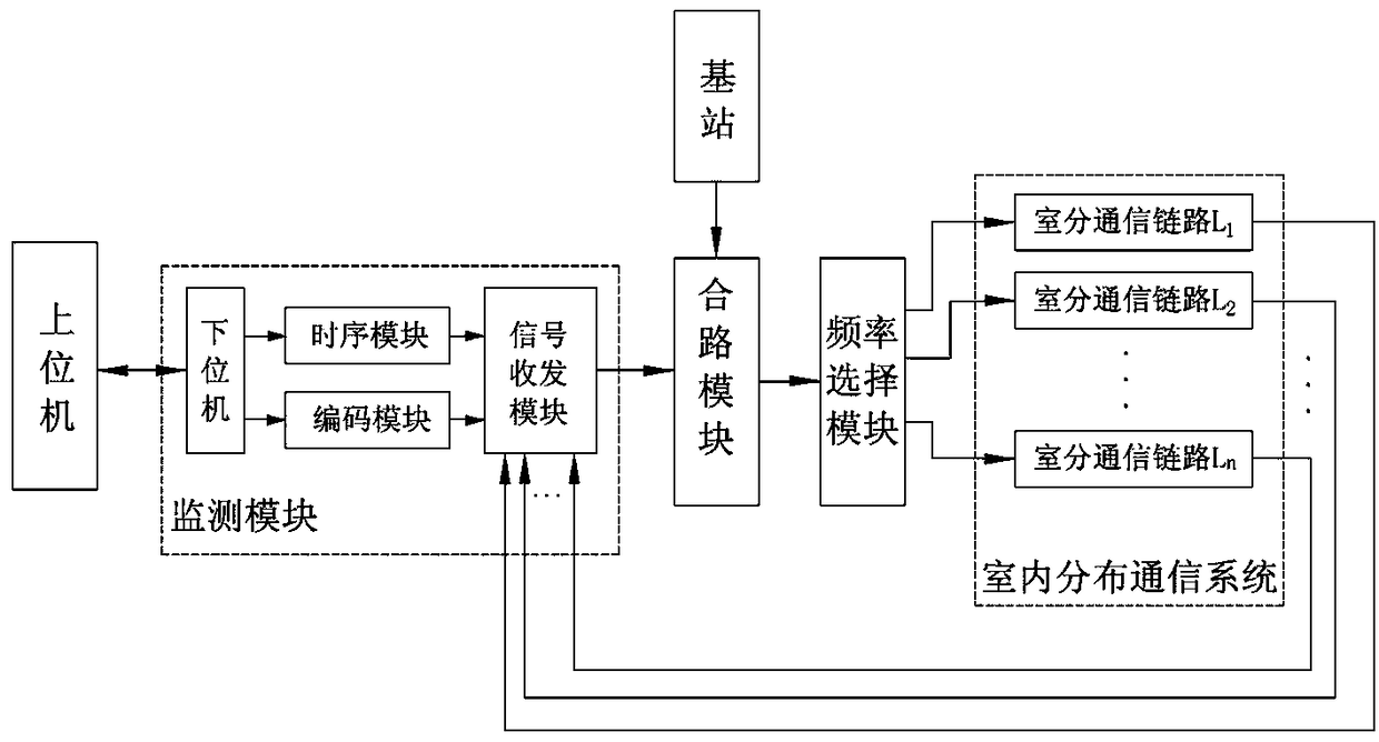
[0055] The upper computer is used for parameter setting and result analysis and display, and sends the control information to the monitoring equipment through the network. The monitoring module generates multiple sets of signals with different codes and frequencies for the detected room subsystem according to the settings of the upper computer and selects them through frequency selection. The device is transmitted to the link of the monitored indoor communication system to realize the online status monitoring of the indoor communication system.

[0056] The encoding module is used for encoding and identifying links...

Embodiment 2

[0078] The difference between this embodiment and Embodiment 1 is that, if Figure 5 As shown, the frequency selector includes a high-pass filter and a band-stop filter, the input of the high-pass filter is connected to the coupling port of the corresponding coupler, the output of the high-pass filter is connected to the input of the corresponding band-stop filter, and the band-stop filter The output terminal of is connected to the input terminal of the corresponding room division communication link, and the output terminal of the band-stop filter sends the room division signal S and the screened monitoring signal to the corresponding room division communication link.

[0079] As mentioned above, the frequency of the monitoring signal is lower than the room division signal S, and the limited number screening is realized through the high-pass filter + band-stop filter scheme, and the high-pass filter filters out the room division communication link L i+1 to L n The monitoring ...

Embodiment 3

[0090] The difference between this embodiment and Embodiment 1 and Embodiment 2 is that, as Figure 6 shown, the frequency selector F i set on the coupler C i and coupler C i+1 between, where, the last frequency selector F n-1 in series with the coupler C n-1 And indoor communication link L n Between, the frequency selector uses a high-pass filter, the frequency selector F i Filter and remove room communication link L i+1 To indoor communication link L n Corresponding monitoring signal S i+1 to S n .

[0091] Compared with Embodiment 1 and Embodiment 2, the monitoring module does not change in this embodiment, and the parameters of the host computer and the frequency selector are set in one-to-one correspondence, wherein the frequency selector is installed on the coupler or function of the indoor communication link. After the divider, the selection and filtering of the monitoring signal is realized. The frequency selector uses a high-pass filter, and n-1 high-pass fi...


PUM


Abstract

The invention discloses an indoor distribution communication system monitoring device and method; the indoor distribution communication system monitoring device comprises an upper computer, a monitoring module, a combiner module and a frequency selection module; the communication end of the upper computer is connected with the communication end of the monitoring module; the output end of the monitoring module is connected with the monitoring signal input end of the combiner module; an indoor distribution signal input end of the combiner module is connected with an external base station; and the output end of the combiner module is connected with the input end of the indoor distribution communication system. According to the monitoring device and the monitoring method, the frequency selection module is arranged in the indoor distribution communication link; the functions of parameter setting, frequency setting and the like of the monitoring module are matched, so that simultaneous real-time monitoring of a plurality of different links is realized, and fault positioning monitoring and blind-spot-free monitoring are achieved; fault information alarming and positioning are accurate andreal-time; the communication system link in the detected indoor distribution system is monitored in real time, and fault analysis can be carried out; besides, complete monitoring of devices in the indoor distribution system of a coupler, a power divider, a leaky cable, a feeder line, an antenna and the like is realized.

Description

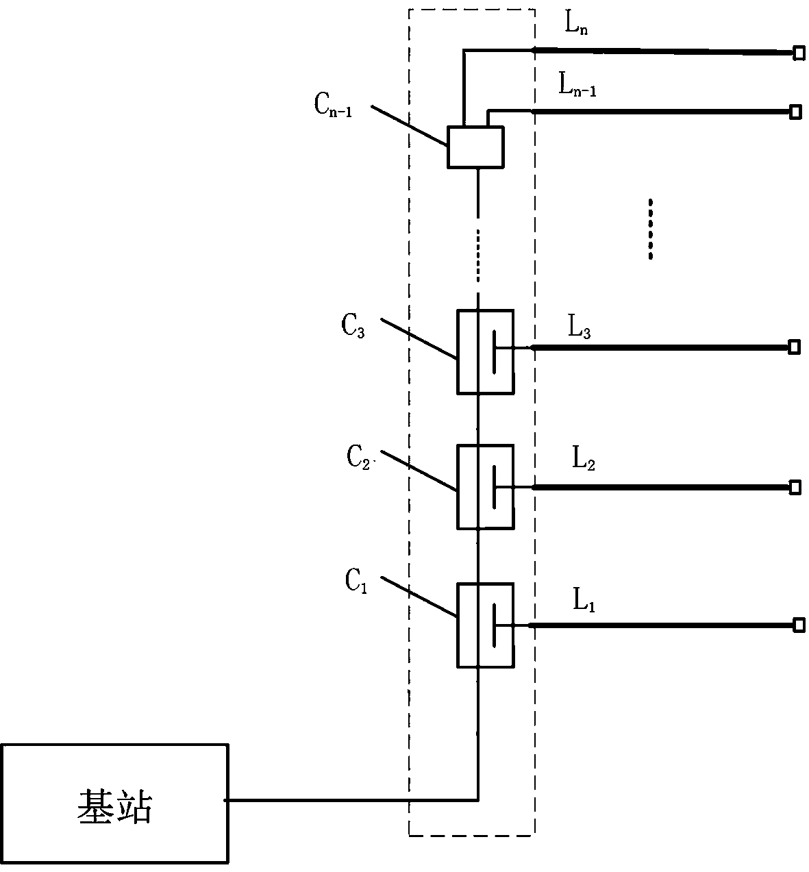
technical field [0001] The invention relates to the technical field of indoor distributed communication system monitoring, in particular to a monitoring device and method for an indoor distributed communication system. Background technique [0002] With the development of the economy and the popularization of mobile communications, users' requirements for the quality of communication services are also increasing. At present, buildings are getting higher and higher, and base station coverage alone is far from meeting the communication quality required by users. Therefore, indoor coverage is now One of the most effective ways. In the process of indoor coverage, passive devices such as couplers, power splitters, leaky cables, feeders, and antennas are often used for coverage, such as figure 1 As shown, the indoor distributed communication system includes a coupler C 1 to C n-1 and n parallel indoor communication links L 1 to L n , the indoor communication links are connecte...

Claims


Application Information

Patent Timeline
Patent Type & Authority Applications(China)
IPC IPC(8): H04W24/04H04W24/08
CPCH04W24/04H04W24/08
Inventor 王志辉尚爱民王胜军郭明明马鸿志王如彬白龙刚
Owner TONGHAO CABLE GRP CO LTD
Learn More