Supercharge Your Innovation With Domain-Expert AI Agents!

Electric valve

A technology of electric valve and valve seat, which is applied in the direction of valve lift, valve details, valve device, etc., which can solve the problems of easy deflection, vibration, and low precision of the valve core, and achieve improved fixing accuracy, good wear resistance, and high thread accuracy Effect

Active Publication Date: 2018-08-21
浙江中宝自控元件有限公司
View PDF6 Cites 0 Cited by
  • Summary
  • Abstract
  • Description
  • Claims
  • Application Information

AI Technical Summary

Problems solved by technology

[0003] Aiming at the problem that the valve core is easy to deflect and vibrate due to the low accuracy of the split structure of the internal threaded parts of the existing electric valve, the present invention aims to provide an electric valve

Method used


Image

  • Electric valve
  • Electric valve
  • Electric valve

Examples


Embodiment Construction

[0024] Specific embodiments of the present invention will be described in detail below in conjunction with the accompanying drawings.

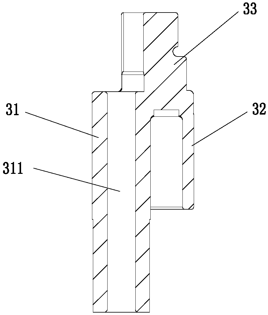
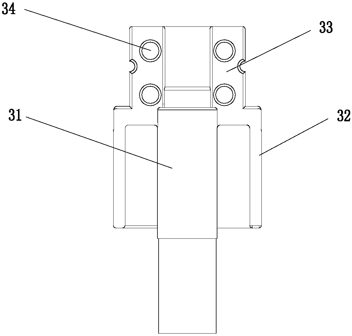
[0025] like Figure 1-Figure 9 As shown, the present invention includes a valve housing 1, a valve seat 5, an internally threaded part 2, an externally threaded part 3, a rotor 6, a valve core 4 and an externally threaded seat 8, and the externally threaded part 3 is threaded on the internally threaded part In the internally threaded hole of 2, the top of the externally threaded part 3 passes through the internally threaded hole, the externally threaded part 3 is provided with a spool guide hole, the spool 4 is mounted in the spool guide hole, and the externally threaded part 3 is divided into two sections, It includes an external thread section 31 and a rotor connecting section 32. The rotor connecting section 32 is in the shape of a semi-cylindrical body with a hollow inner cavity and an open bottom. The top of the external thread section 31...


PUM


Abstract

The invention provides an electric valve which is characterized in that an external thread part is penetrated in an internal thread hole of an internal thread part by virtue of threaded fit; the top of the external thread part penetrates out of the internal thread hole; the external thread part is provided with a valve element guide hole; a valve element is penetrated in the valve element guide hole; the external thread part is divided into two sections, including an external thread section and a rotor connecting section; the rotor connecting section is in a semi-cylindrical shape with a hollow inner cavity and an opened bottom; the top of the external thread section is fixed at the top of the hollow inner cavity of the rotor connecting section; the electric valve also comprises an external thread base; the external thread base and the rotor connecting section are symmetrically arranged; the rotor connecting section is matched with the external thread base to form a cylinder; and the cylinder is penetrated in a center through hole of a rotor in a matched mode. The cooperation of semi-cylindrical positioning parts ensures that the existing assembly mode is easier, and the external thread part ensures the integrity of external threads and a guide section, reduces the frictional resistance of internal threads of the internal thread part and the external threads and improves the screwing precision and the guide precision.

Description

technical field [0001] The invention belongs to the technical field of electric valves, and in particular relates to an electric valve. Background technique [0002] Patent Publication No. CN202992195U discloses an electric valve for regulating fluid flow. The valve seat is welded to the connecting pipe to form a valve seat assembly, and the external threaded part and the valve seat assembly are integrally injection molded. The internal thread component (integrated structure with the rotor) is divided into two halves from the center, and two half threads are formed by injection molding respectively, and then merged to form a whole internal thread. After the internal thread components are combined, the spring accommodation chamber and the valve needle installation and positioning structure are formed. Although this technology reduces the parts of the electric valve, the internal thread parts are divided into two parts. After merging, there must be differences in size and posi...

Claims


Application Information

Patent Timeline
Patent Type & Authority Applications(China)
IPC IPC(8): F16K1/32F16K31/50
CPCF16K1/32F16K31/50Y02B30/70
Inventor 王林炜
Owner 浙江中宝自控元件有限公司
Features
  • R&D
  • Intellectual Property
  • Life Sciences
  • Materials
  • Tech Scout
  • Unparalleled Data Quality
  • Higher Quality Content
  • 60% Fewer Hallucinations
Learn More