Mold device and method of using the same

A technology on the mold and mold side, applied in the direction of forming tools, manufacturing tools, piercing tools, etc., can solve problems such as deterioration of dimensional accuracy and shape accuracy, uneven wear, and burrs on products, and achieve the effect of suppressing misalignment

Active Publication Date: 2019-09-13
MITSUI HIGH TEC INC
View PDF10 Cites 0 Cited by
  • Summary
  • Abstract
  • Description
  • Claims
  • Application Information

AI Technical Summary

Problems solved by technology

There are problems in that uneven wear occurs in sharpened objects (punch 84 and die 86), burrs are generated in products, and dimensional accuracy and shape accuracy deteriorate

Method used


Image

  • Mold device and method of using the same
  • Mold device and method of using the same
  • Mold device and method of using the same

Examples


Embodiment Construction

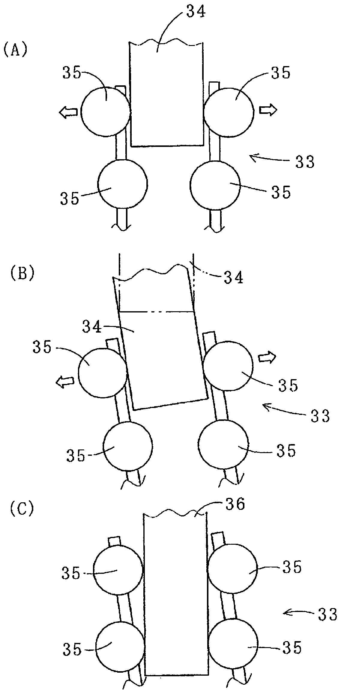
[0091] figure 1 (A) is a schematic view illustrating a state in which a guide post having an outer diameter such that the balls 35 of the ball retainer 33 are largely moved outward in the radial direction thereof is inserted into the ball cage 33 in a vertical state .

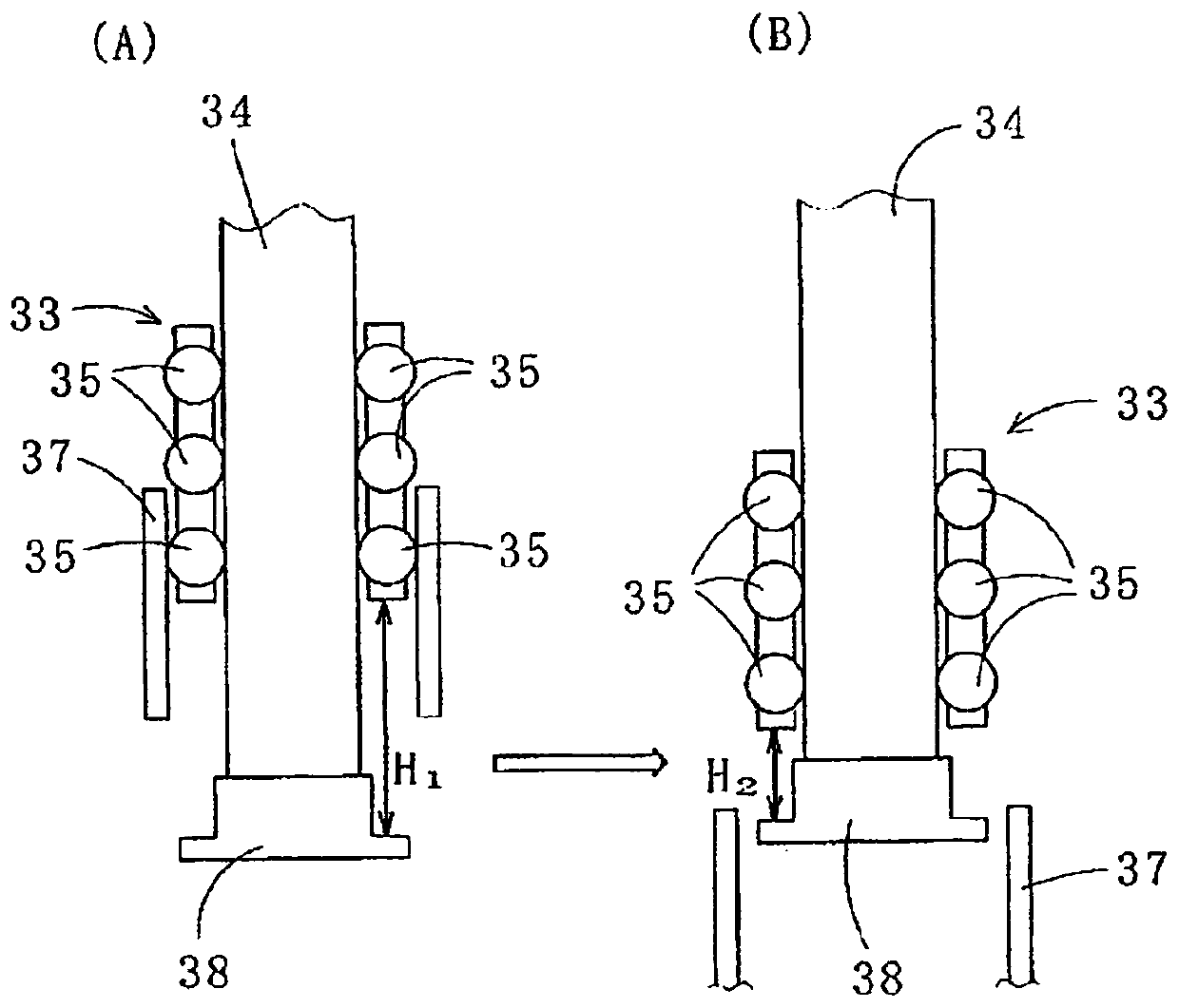
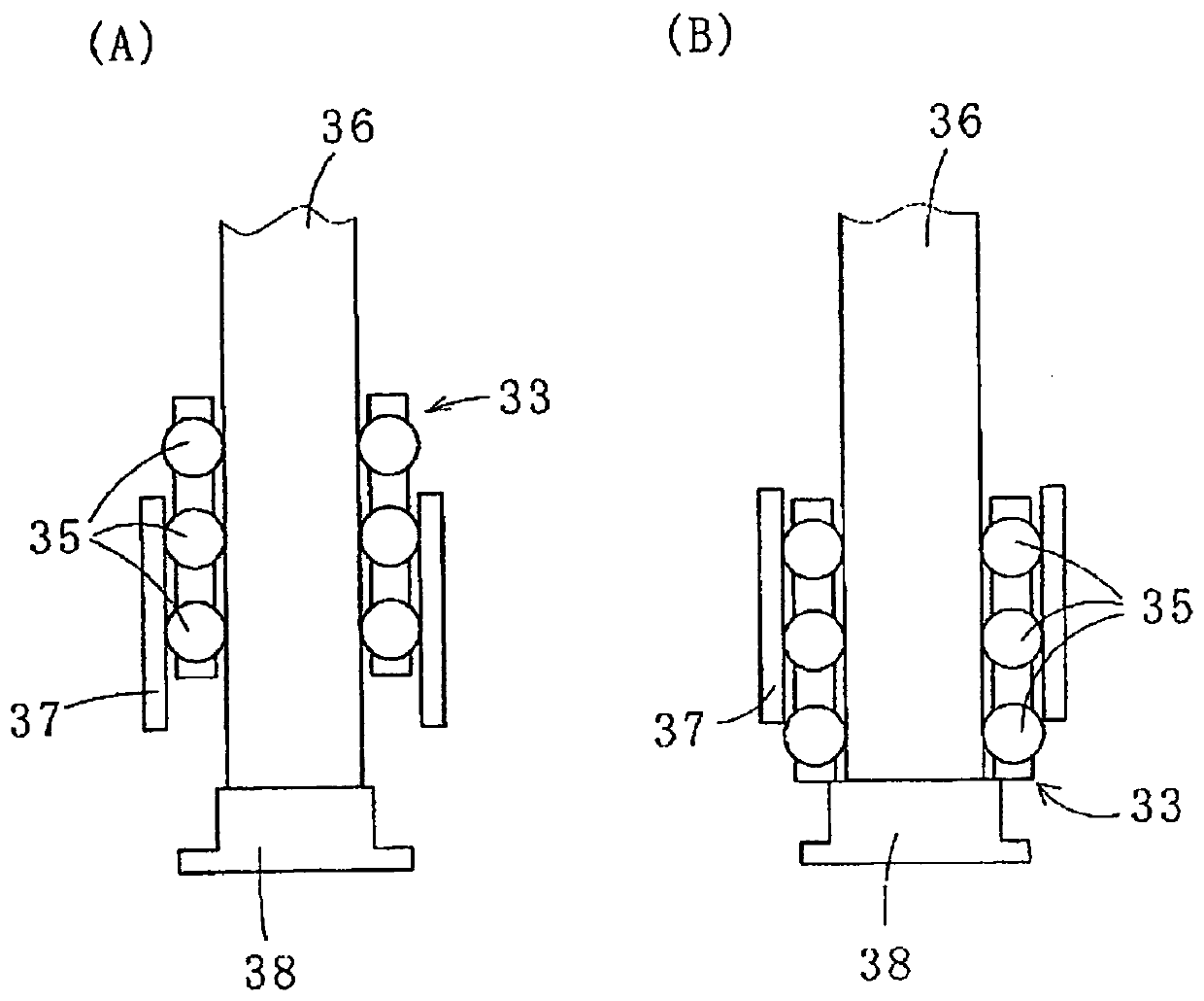
[0092] figure 1(A) Figure shows that the guide post 34 is inserted into the guide sleeve 37 through the ball retainer 33 along the axial direction of the guide sleeve 37 (see figure 2 (A) and 2(B)). In this case, the balls 35 of the ball cage 33 move (squeezed) radially outward of the ball cage 33 (guide pin 34 ) along the outer diameter of the guide pin 34 while rotating in contact with the guide pin 34 . out). Pressing force is applied to the inner surface of the guide sleeve 37 through the balls 35 moving outward in the radial direction. The retaining force from the guide sleeve 37 is applied to the guide post 34 due to the reaction force of the pressing force. As a result, the guide post 34 can smo...


PUM


Abstract

A die set (10) is provided comprising a stripper plate holder (19) supported by a plurality of guide posts (15) to be attached to a punch press The upper die (12) of the sliding plate (11) is connected to the lower die (14) attached to the punch backing plate (13), and the stripper plate holder (19) moves up and down together with the upper die (12), and The stripper plate holder (19) guides the punch (16) provided in the upper die (12) to the die hole (18) of the die (17) provided in the lower die (14). The guide column (15) includes an upper guide column (29), which is fitted to the upper guide sleeve (27) of the upper mold (12) by an upper ball retainer (28), and the ejector plate retainer (19) is interconnected with upper mold (12). The upper guide post (29) has a stepped shape in which the lower post part (32) on the stripper plate holder (19) side has a smaller diameter than the upper post part (31) on the upper mold (12) side.

Description

technical field [0001] The invention relates to a mold device and a method for using the mold device. Background technique [0002] like Figure 8 As shown, in the die set 80 , a workpiece 81 to be punched is pressed against a lower die 82 using a stripper plate 85 , and then an upper die 83 is moved downward so that it is punched by a punch 84 provided in the upper die 83 The blanked workpiece 81 . The stripper plate holder 88 holds the stripper plate 85 and guides the punch 84 to the die hole 87 of the die 86 provided in the lower die 82 . The stripper plate holder 88 is provided to freely move back and forth with respect to the lower mold 82 . As a result, products requiring high dimensional accuracy and shape accuracy are punched out. [0003] Upper die 83 includes: punch plate 89, which holds punch 84; punch back plate 90, which supports punch plate 89; and punch holder (upper die base) 91, This punch holder 91 attaches the punch back plate 90 to a punch slide plate...

Claims


Application Information

Patent Timeline
Patent Type & Authority Patents(China)
IPC IPC(8): B21D37/10B21D28/04B21D28/34B30B15/04
CPCB21D28/04B21D28/34B21D37/10B30B15/04
Inventor 宗冈秀策鹈木一茂日向寺伦纪
Owner MITSUI HIGH TEC INC
Why Eureka
Try Eureka