Lime stirrer with uniform stirring function

A technology of evenly stirring and mixing machine, applied in the field of lime mixer, can solve the problems of poor wall painting and insufficient mixing of lime, and achieve the effect of convenient movement and use, and even mixing

Inactive Publication Date: 2018-08-24
芜湖市涵润智能科技有限公司
View PDF5 Cites 4 Cited by
  • Summary
  • Abstract
  • Description
  • Claims
  • Application Information

AI Technical Summary

Problems solved by technology

[0002] The lime mixer, that is, the horizontal shaft mortar mixer, is composed of a mixing drum, a stirring shaft, a transmission device and a bottom frame. With the rotation of the shaft, the mixture in the mixing drum is forcibly stirred under the action of the mixing blades. Small-capacity mortar mixers are generally mobile, relying on manual feeding, and the mixing drum is tilted to discharge materials. Large-capacity mortar mixers are mobile There are two kinds of type and fixed type. Some mortar mixers are also equipped with a feeding device and a water tank. When preparing a small amount of mortar, a vertical shaft type mortar mixer can also be used. The mixing drum of this mixer is a cylinder placed horizontally, and the center of the cylinder There is a rotating vertical shaft, and several sets of mixing blades are installed on the arm frame of the vertical shaft. With the rotation of the vertical shaft, the mixture in the mixing drum is strongly stirred by the blades, and the mixed mortar is discharged from the discharge door at the bottom of the mixing drum; The particles of lime itself are large and small, and most of the lime mixers in the market today mix without crushing, resulting in insufficient mixing of large particles of lime, which is not good for the later wall painting

Method used


Image

  • Lime stirrer with uniform stirring function
  • Lime stirrer with uniform stirring function
  • Lime stirrer with uniform stirring function

Examples


Embodiment Construction

[0023] The following will clearly and completely describe the technical solutions in the embodiments of the present invention with reference to the accompanying drawings in the embodiments of the present invention. Obviously, the described embodiments are only some, not all, embodiments of the present invention. Based on the embodiments of the present invention, all other embodiments obtained by persons of ordinary skill in the art without making creative efforts belong to the protection scope of the present invention.

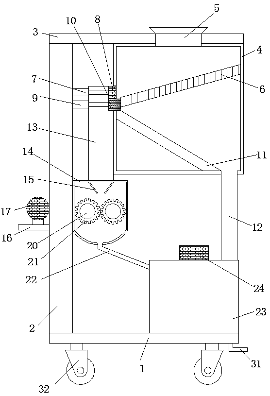
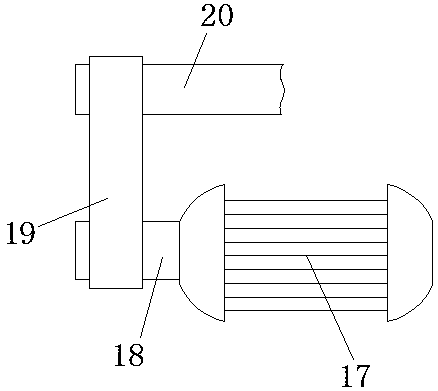
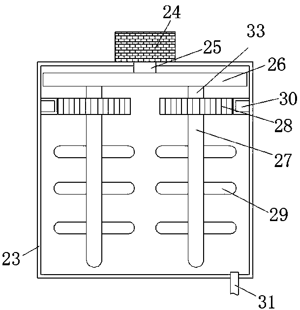
[0024] Embodiments of the present invention provide a lime mixer that stirs evenly, such as Figure 1-5 As shown, including the base 1, the bottom of the base 1 is fixedly equipped with universal wheels 32. By setting the universal wheels 32, the lime mixer can be moved arbitrarily, which is convenient to move and use. The left side of the top of the base 1 is fixedly equipped with a support column 2 A support plate 3 is fixedly installed on the top of the sup...


PUM


Abstract

The invention provides a lime stirrer with the uniform stirring function, and relates to the field of building construction. The lime stirrer comprises a base, universal wheels are fixedly installed at the bottom of the base, a supporting column is fixedly installed on the left side of the top of the base, a supporting plate is fixedly installed at the top of the supporting column, and a screen box is fixedly installed on the right side of the bottom of the supporting plate; a screen is fixedly installed on the inner wall of the screen box, a sliding plate is fixedly installed at the bottom ofthe inner cavity of the screen box, and the end, far away from the bottom of the inner cavity of the screen box, of the sliding plate is fixedly connected with the left wall of the inner cavity of the screen box; and a coarse material pipe is arranged on the left side of the screen box, and the coarse material pipe penetrates through the left wall of the screen box. According to the lime stirrerwith the uniform stirring function, two stirring shafts are arranged, so that stirring is uniform; gear shafts are arranged to cooperate with bearing grooves so that gears can move; the ring-shaped rack is arranged to be meshed with the gears, so that when a rotating disc rotates, the gears drive the stirring shafts, meanwhile, the gears rotate, and stirring is more uniform.

Description

technical field [0001] The invention relates to the technical field of building construction, in particular to a lime mixer for uniform mixing. Background technique [0002] The lime mixer, that is, the horizontal shaft mortar mixer, is composed of a mixing drum, a stirring shaft, a transmission device and a bottom frame. With the rotation of the shaft, the mixture in the mixing drum is forcibly stirred under the action of the mixing blades. Small-capacity mortar mixers are generally mobile, relying on manual feeding, and the mixing drum is tilted to discharge materials. Large-capacity mortar mixers are mobile There are two kinds of type and fixed type. Some mortar mixers are also equipped with a feeding device and a water tank. When preparing a small amount of mortar, a vertical shaft type mortar mixer can also be used. The mixing drum of this mixer is a cylinder placed horizontally, and the center of the cylinder There is a rotating vertical shaft, and several sets of mix...

Claims


Application Information

Patent Timeline
IPC IPC(8): B28C3/00
CPCB28C3/00
Inventor 蔡敬东
Owner 芜湖市涵润智能科技有限公司
Why Eureka
Try Eureka