Travelling transporter and storage cabinet

A technology of conveying device and storage unit, which is applied in the field of cargo storage, can solve the problems of high labor intensity, energy consumption, and low work efficiency, and achieve the effect of convenient transportation, simple structure and reasonable design

Pending Publication Date: 2018-08-24
WUHAN POLYTECHNIC UNIVERSITY
0 Cites 0 Cited by

AI-Extracted Technical Summary

Problems solved by technology

[0003] The existing storage cabinets use the method of manually storing goods one by one. Workers need to take the goods and transport them to the empty s...

Method used

And the side of the first slide block 146 and the second slide block 148 away from the connecting rod 144 is all fixedly provided with a pallet 16, the pallet 16 is used to place goods and transport, when storing goods, the movement of the connecting rod 144 drives The two sliders slide, and the sliders drive the tray 16 to move along the slide rails, so that two goods can be stored in different storage units 202 at the same time, which greatly improves the storage efficiency.
The quantity of slide rail is also at least two, and slide block is respectively embedded in different slide rai...

Abstract

The invention discloses a travelling transporter and a storage cabinet, and relates to the storage technical field of goods such as express items. The travelling transporter comprises a pedestal and acrankshaft slide block mechanism, wherein at least two slide rails are arranged on the pedestal; the crankshaft slide block mechanism comprises a connecting rod and at least two slide blocks which are arranged on the connecting rod in a spaced mode; and the slide block is hinged with the connecting rod. The slide blocks are separately embedded into different slide rails, and the slide blocks simultaneously slide in corresponding slide rails under action of the connecting rod. The travelling transporter is reasonable in design, is simple in structure, and is convenient and stable in transportation; a power source drives the connecting rod to move, and the connecting rod simultaneously drives the two slide blocks to slide in different slide rails, so that the effect of driving two shafts tolink through single shaft rotation is realized, and therefore, working efficiency is improved, labor intensity is reduced, practicability is high, and range of application is wide.

Application Domain

ConveyorsStorage devices

Technology Topic

EngineeringCrankshaft +1

Image

  • Travelling transporter and storage cabinet
  • Travelling transporter and storage cabinet
  • Travelling transporter and storage cabinet

Examples

  • Experimental program(2)

Example Embodiment

[0041] Example 1
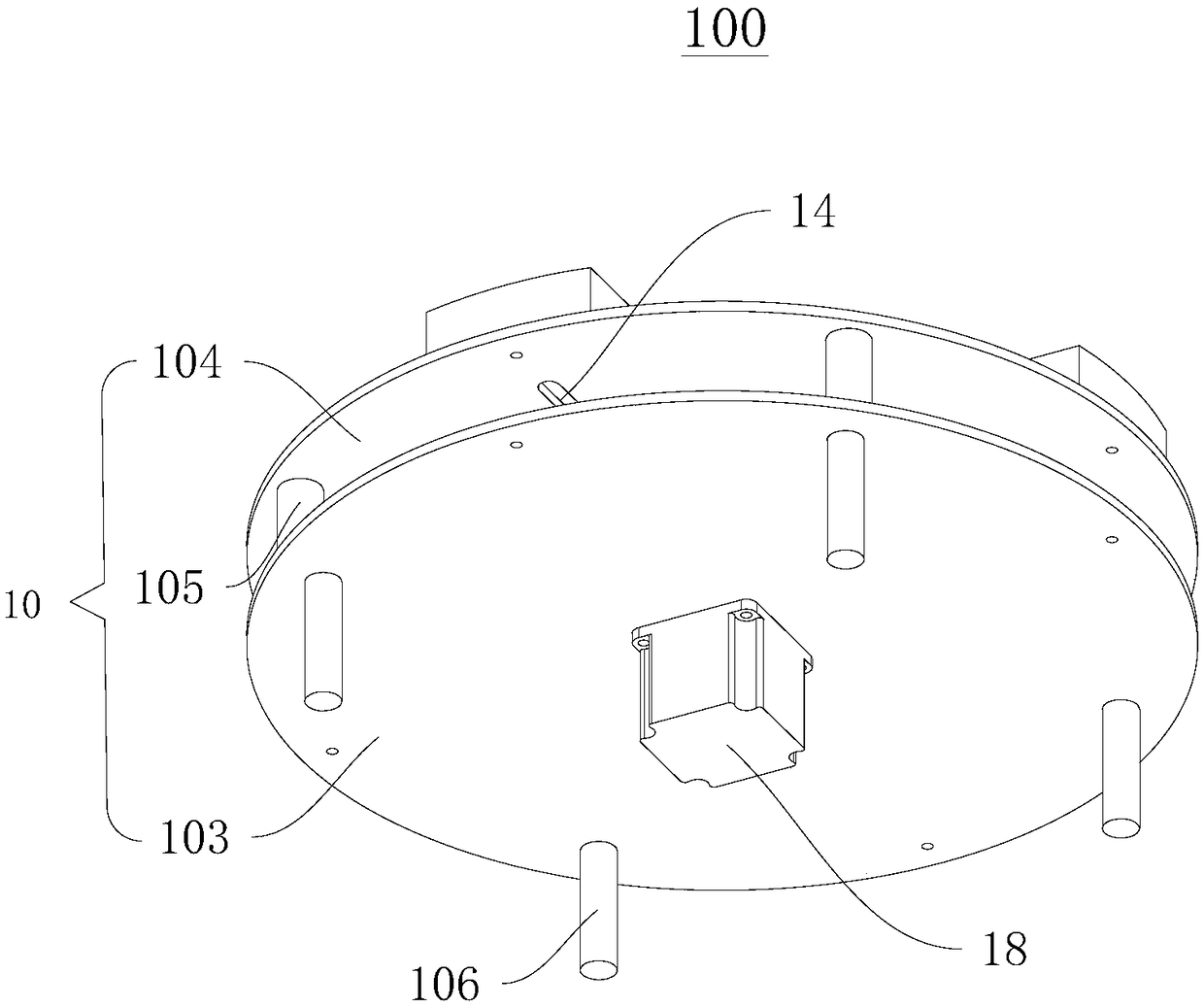
[0042] figure 1 It is a structural schematic diagram of the first viewing angle of the walking conveying device 100 provided in this embodiment, figure 2 A schematic structural diagram of the second viewing angle of the walking conveying device 100 provided in this embodiment. Please refer to figure 1 and figure 2 shown.
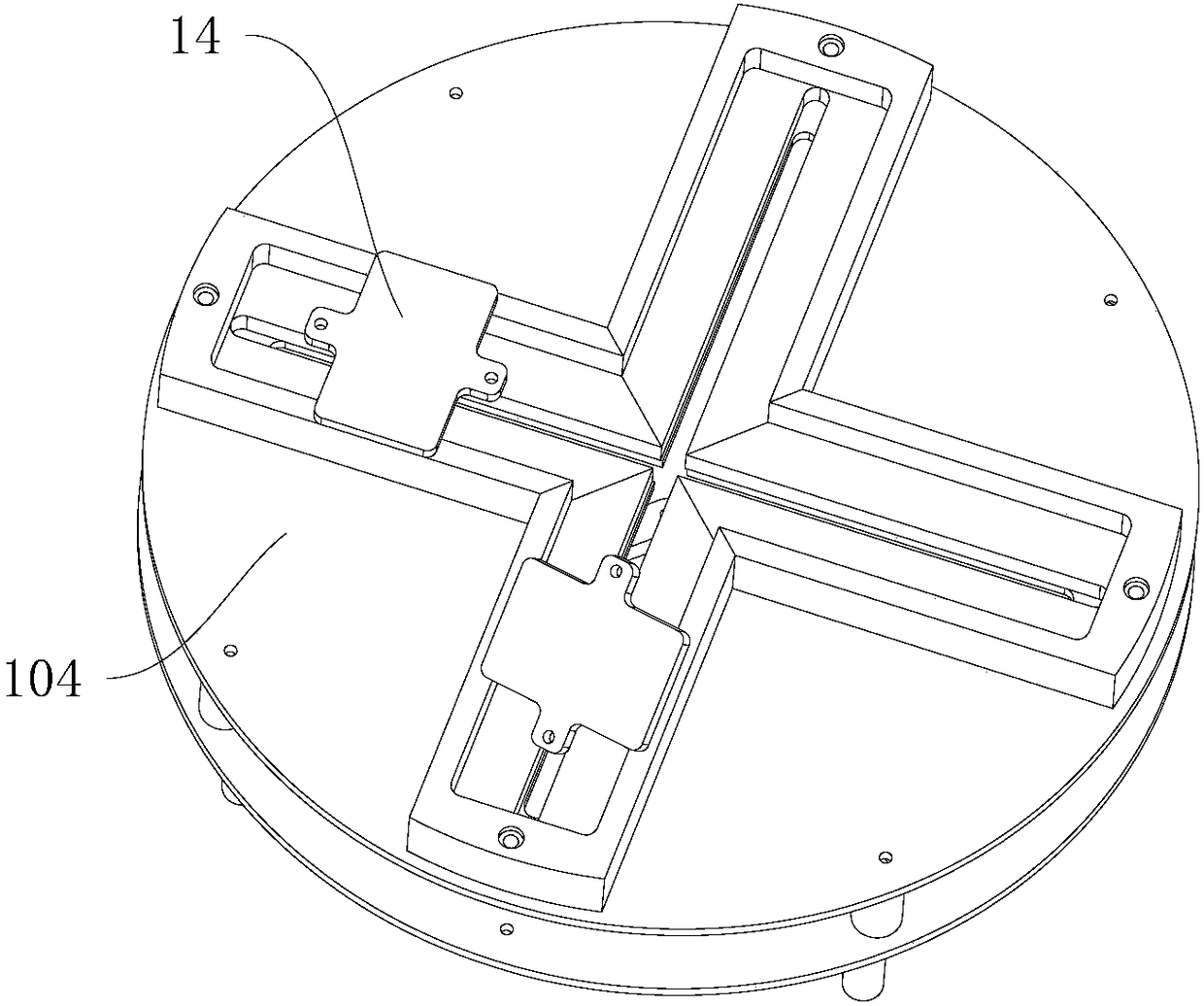
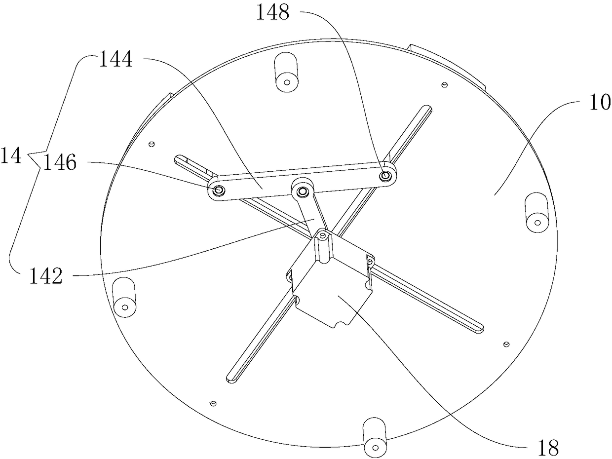
[0043] The walking conveyor 100 includes a base 10 , a slider crank mechanism 14 and a power source 18 . The base 10 is provided with slide rails. The crank slider mechanism 14 is disposed on the base 10 and the slider is slidably disposed in the slide rails. The power source 18 is fixedly disposed on the base 10 and drives the crank 142 to rotate.
[0044] Please continue to refer to figure 1 As shown, the base 10 includes a base 103, a walking table 104 and a connecting column 105, the base 103 and the walking table 104 are arranged in parallel, the connecting column 105 is located between the base 103 and the walking table 104 and connects the base 103 and the walking table 104 fixed connections.
[0045] Please continue to refer to figure 1 and figure 2 As shown, the slide rail is set on the walking table 104, the crank slider mechanism 14 is located between the base 103 and the walking table 104, and the power source 18 is fixedly arranged on the side of the base 103 away from the walking table 104.
[0046] The base 103 is provided with a through hole, and the power output shaft of the power source 18 is fixedly connected with the crank 142 after passing through the through hole. Drive the slider to move along the slide rail.
[0047] Optionally, a support assembly is provided on the side of the base 103 facing away from the walking workbench 104 . The support assembly includes a plurality of supports 106 , and the plurality of supports 106 are evenly distributed and fixed on the base 103 for supporting the entire base 10 .
[0048]Both the base 103 and the walking workbench 104 are in the shape of a circular plate, and the shape of the cabinet body 20 is also columnar to match it. The walking workbench 104 is provided with at least two slide rails, and the two slide rails are arranged crosswise, including vertically arranged .
[0049] image 3 The structure schematic diagram of the cooperation of the crank slider mechanism 14 and the base 10 in the walking conveying device 100 provided in this embodiment from a first viewing angle.
[0050] Figure 4 A structural schematic diagram of the cooperation between the slider crank mechanism 14 and the base 10 in the walking conveyor 100 provided in this embodiment from a second perspective. Please refer to image 3 and Figure 4 shown.
[0051] The slider crank mechanism 14 includes a crank 142, a connecting rod 144 and a slider, wherein the power source 18 is fixedly arranged on the base 10 and the power source 18 includes a power output shaft, the power output shaft is fixedly connected to the crank 142, and the crank 142 is connected to the connecting rod. 144 is hinged, and the two ends of the connecting rod 144 are respectively provided with sliders, and the sliders are correspondingly arranged in the slide rails and can slide in the slide rails.
[0052] Optionally, there are at least two sliders, and all the sliders are spaced apart from the connecting rod 144 , and each slider is hinged to the connecting rod 144 .
[0053] The quantity of slide rail is also at least two, and slide block is embedded in different slide rail respectively, and the quantity of connecting rod 144 is one and all slide blocks are arranged on the connecting rod 144 at intervals, under the effect of connecting rod 144, all sliding The blocks can slide simultaneously in the corresponding slide rails, so as to achieve the purpose of linkage.
[0054] In this embodiment 1, the number of sliders is two and they are the first slider 146 and the second slider 148 respectively, and the number of slide rails is two and they are respectively the first slide rail 107 and the second slide rail 108, The first sliding rail 107 and the second sliding rail 108 are arranged crosswise, and the first sliding block 146 and the second sliding block 148 are respectively located at two ends of the connecting rod 144 .
[0055] The crank 142 and the connecting rod 144 are hinged at the middle position of the connecting rod 144 along the length direction, the first sliding block 146 is slidably embedded in the first sliding rail 107, and the second sliding block 148 is slidably embedded in the second sliding rail 108.
[0056] In this embodiment 1, the first slide rail 107 and the second slide rail 108 are arranged vertically, the crank 142 drives the connecting rod 144 to move, and the connecting rod 144 simultaneously drives the sliding of the first slider 146 and the second slider 148, realizing linkage .
[0057] And the side of the first slider 146 and the second slider 148 away from the connecting rod 144 is fixedly provided with a tray 16, the tray 16 is used to place the goods and convey them, when the goods are stored, the movement of the connecting rod 144 drives the two sliders. The block slides, and the slide block drives the tray 16 to move along the slide rails, so as to store two goods into different storage units 202 at the same time, which greatly improves the storage efficiency.
[0058] The beneficial effects of the walking conveying device 100 provided in Embodiment 1 of the present invention are:
[0059] The design is reasonable, the structure is simple, and the transportation is convenient and stable. The power source 18 drives a connecting rod 144 to move, and the connecting rod 144 simultaneously drives two sliders to slide in different slide rails, realizing the effect of single-axis rotation driving two-axis linkage.
[0060] When the walking conveying device 100 is applied in the storage cabinet 200 , the goods can be put into the fixed inventory window 205 and reach different storage units 202 . For the storage of goods in the existing storage cabinet 200, it avoids the physical exertion of the staff carrying back and forth when releasing the goods one by one, and also prevents the staff from being inconvenient to store goods due to factors such as height.

Example Embodiment

[0061] Example 2
[0062] Embodiment 2 of the present invention provides a storage cabinet 200 , which includes a cabinet body 20 and the walking conveying device 100 provided in Embodiment 1. The walking conveying device 100 is located inside the bottom of the cabinet body 20 .
[0063] Figure 5 It is a schematic structural diagram of the storage cabinet 200 provided in Embodiment 2, Image 6 A schematic structural diagram of the cabinet body 20 in the storage cabinet 200 provided in the second embodiment. Please refer to Figure 5 and Image 6 shown.
[0064] The cabinet body 20 is a columnar structure, and its projection on the horizontal plane is a cross-shaped structure and includes two lockers. The two lockers are intersected to form four storage areas, wherein the first slide rail in Embodiment 1 107 is located in one of the lockers, the second slide rail 108 is located in the other locker, and the walking conveyor 100 slides along the first slide rail 107 and the second slide rail 108 .
[0065] When the first slider 146 and the second slider 148 in the walking conveying device 100 are respectively embedded in the first slide rail 107 and the second slide rail 108, the two walking conveying devices 100 move along the first slide rail 107 and the second slide rail 108 respectively. The second sliding rail 108 slides synchronously, so that two goods can be transported at the same time.
[0066] Each storage area includes a conveying channel and cabinet assemblies located on both sides of the conveying channel. Each cabinet assembly includes a plurality of storage units 202 arranged in sequence. The storage units 202 are arranged in multiple rows and columns, and the walking conveyor 100 can Transport the goods to each row of the cabinet body 20 , and cooperate with the vertical traveling mechanism and the pushing mechanism to match the goods to be stored with any one of the storage units 202 , thereby storing the goods to be stored in the storage unit 202 .
[0067] The cabinet body 20 is fixedly provided with an inventory window 205, and the inventory window 205 is opened at the end of the conveying passage, both sides of the conveying passage are storage units 202, and the end of the conveying passage away from the inventory window 205 is also provided with a maintenance or inspection passage.
[0068] When storing goods, the staff puts the goods to be stored from the inventory window 205, and the walking conveyor 100 transports the goods to be stored to a suitable storage unit 202 for storage.
[0069] The design of the storage cabinet 200 conforms to the principles of ergonomics, and storage cabinets 200 of different sizes are provided to meet the storage requirements of goods of different sizes. The storage channel and the storage unit 202 are stable, thereby ensuring that the goods enter the storage unit 202 smoothly. .
[0070] Each storage unit 202 is provided with a cabinet door externally, and an electromagnet is provided on the cabinet door, and the opening and closing of the cabinet door is controlled by the electromagnet, thereby greatly improving the storage efficiency and the space utilization rate of goods storage.
[0071] It can be understood that the storage cabinet 200 is a large-scale intermediate storage station, which can also be put into residential areas, public places, and used to replace the existing express sorting stations. Due to the characteristics of the operating mechanism, the storage cabinet 200 has a unique and stylish appearance. Small footprint, high space utilization, expanded storage space, and strong practicability.
[0072] The beneficial effects of the storage cabinet 200 provided by Embodiment 2 of the present invention are:
[0073] The design is reasonable, the storage is convenient and stable, the storage efficiency is greatly improved, the space utilization rate is improved, the practicability is strong, the work intensity of the staff is reduced, and the goods can be classified and stored according to the size of the goods, which is safe and reliable, and has a wide range of applications.

PUM

no PUM

Description & Claims & Application Information

We can also present the details of the Description, Claims and Application information to help users get a comprehensive understanding of the technical details of the patent, such as background art, summary of invention, brief description of drawings, description of embodiments, and other original content. On the other hand, users can also determine the specific scope of protection of the technology through the list of claims; as well as understand the changes in the life cycle of the technology with the presentation of the patent timeline. Login to view more.

Similar technology patents

Stator assembly for asynchronous motor and method for making same

InactiveCN101043154AEasy to windreasonable design
Owner:GUANGDONG WELLING ELECTRIC MACHINE MFG

Displacement-crawler-type pipe dredging robot

Owner:CHINA UNIV OF GEOSCIENCES (WUHAN)

Classification and recommendation of technical efficacy words

  • Simple structure
  • reasonable design

Sharing system for air-conditioning coat

InactiveCN107440179ASimple structureeasy to wear
Owner:QINGDAO HAIER AIR CONDITIONER GENERAL CORP LTD

Feeding device of sorter of batteries plate

InactiveCN101357717ASimple structurecooperate well
Owner:NANJING NORMAL UNIVERSITY

Emergency parachuting device and method for multiple-rotor unmanned aerial vehicle

InactiveCN103895870Aavoid aircraft crashSimple structure
Owner:SOUTH CHINA AGRI UNIV +1

Embedding accuracy control construction method for embedded part of overlong equipment foundation platform

InactiveCN102134879Areasonable designSimple construction steps
Owner:SCEGC NO 6 CONSTR ENG GRP CO LTD
Why Eureka
Try Eureka