

A rotary structure of a three-dimensional garage lifting platform
A technology of a slewing structure and a three-dimensional garage, which is applied to the buildings, building types, buildings, etc. where cars are parked, can solve the problem that the vehicle cannot be clamped and fixed, and achieve the effect of preventing falling.
- Summary
- Abstract
- Description
- Claims
- Application Information
AI Technical Summary
Problems solved by technology
Method used
Image

Examples
specific Embodiment approach 1
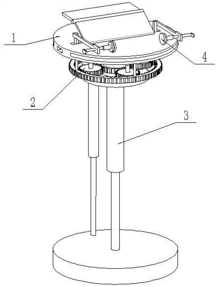
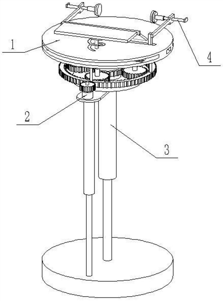
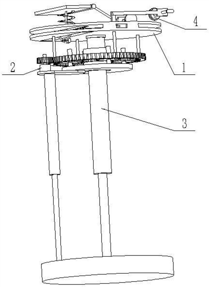
[0033] Such as Figure 1-11As shown, a rotary structure of a three-dimensional garage lifting platform includes a lifting platform assembly 1, a lifting control assembly 2, a lifting support platform assembly 3 and a vehicle fixing clamping device 4, and the lifting platform assembly 1 includes an upper lifting platform 1-1 , support block, lower lifting platform 1-2, cylindrical rod 1-3, fixed ring 1-4, inner ring gear 1-5 and outer gear ring 1-6; The two sides of the top of the lower lifting table 1-2 are connected by two supporting blocks; the middle end of the upper lifting table 1-1 is provided with a rectangular chute 1-1-1, and the front end of the upper lifting table 1-1 is provided with a groove Through holes; the front end of the lower lifting table 1-2 is provided with a rectangular notch 1-2-1; the bottom of the lower lifting table 1-2 is evenly connected with four cylindrical rods 1-3, and the four cylindrical rods 1 The bottom ends of -3 are respectively fixedly...
specific Embodiment approach 2
[0038] Such as Figure 1-11 As shown, the lifting control assembly 2 includes a driving motor 2-1, a driving gear 2-2, a motor seat plate 2-3, a circular seat plate 2-4, four rotating gears 2-5, and a gear shaft 2-6 , the driven ring gear 2-7 and the rotating connecting pipe 2-8; the output shaft of the driving motor 2-1 is fixedly connected to the driving gear 2-2, and the driving motor 2-1 is connected to the motor seat plate 2-3 by screws , the lower end of the motor seat plate 2-3 is fixedly connected to the top of the sliding sleeve 3-3-1; the ring seat plate 2-4 is connected to the motor seat plate 2-3 by screws; the ring seat plate The top surface of 2-4 is rotated and connected with four gear shafts 2-6, and each of the four gear shafts 2-6 is fixedly connected with a rotating gear 2-5; the driving gear 2-2 is meshed with the outer ring gear 1- 6. The inner ring gear 1-5 meshes with the four rotating gears 2-5, and the inside of the four rotating gears 2-5 meshes with...
specific Embodiment approach 3
[0040] Such as Figure 1-11 As shown, the vehicle fixing and clamping device 4 includes a wheel pressing plate 4-1, a climbing pressing plate 4-2, a pressing bar 4-3, a compression spring 4-4, a pressing block 4-5, a left hinged rod 4-6, Left L-shaped tie rod 4-7, right hinged rod 4-8, right L-shaped tie rod 4-9, left cross slider 4-10, right cross slider 4-11, left clamping fixture 4-12 and right clamp Tighten the fixing device 4-13; the wheel pressure plate 4-1 is fixedly connected to the top of the pressure rod 4-3, and the pressure rod 4-3 is slidingly fitted and connected to the front end of the upper lifting platform 1-1, and the pressure rod 4-3 is put on the top There is a compression spring 4-4, and the two ends of the compression spring 4-4 are respectively fixedly connected to the wheel pressing plate 4-1 and the upper lifting platform 1-1; the rear end of the wheel pressing plate 4-1 is connected to climb the slope through a hinge Pressing plate 4-2, the rear en...
PUM
 Abstract
Description
Claims
Application Information