
Saw cutting clamp support device

The technology of a support device and a fixture device is applied in the direction of clamping device, positioning device, clamping, etc., which can solve the problems of high cost, single applicability, and easy shaking of sawing fixtures, so as to improve reliability, stability, and operation Simple and fast, easy to pick and place effect

Inactive Publication Date: 2017-05-31
NINGBO HONGXIECHENG AUTO PARTS CO LTD
View PDF5 Cites 0 Cited by
  • Summary
  • Abstract
  • Description
  • Claims
  • Application Information

AI Technical Summary

Problems solved by technology

At present, there are two types of sawing fixtures in the industry. One is that it can only clamp and fix one end of a long and curved workpiece. It is easy to shake, which leads to unsatisfactory sawing quality; the other is to rely on the overall large sawing fixture to position and fix the workpiece. This kind of sawing fixture has high cost and single applicability

Method used


Image

  • Saw cutting clamp support device
  • Saw cutting clamp support device
  • Saw cutting clamp support device

Examples


Embodiment Construction

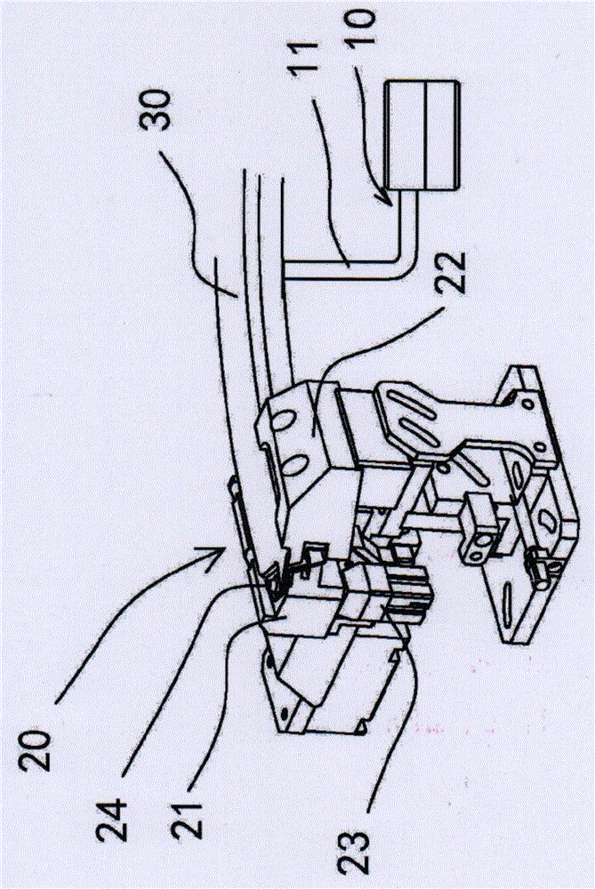
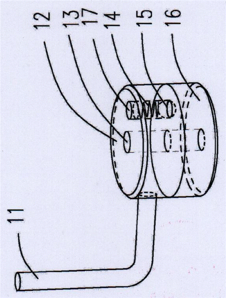
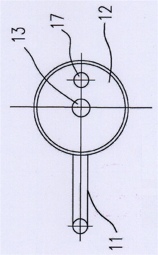
[0021] In order to facilitate the understanding of the present invention, the sawing jig supporting device of the present invention will be more fully described below with reference to the relevant drawings. Preferred embodiments of the invention are shown in the accompanying drawings. However, the present invention can be embodied in many different forms and is not limited to the embodiments described herein. On the contrary, these embodiments are provided to make the understanding of the disclosure of the present invention more thorough and comprehensive.

[0022] Unless otherwise defined, all technical and scientific terms used herein have the same meaning as commonly understood by one of ordinary skill in the technical field of the invention. The terms used herein in the description of the present invention are for the purpose of describing specific embodiments only, and are not intended to limit the present invention.

[0023] The preferred implementation of the sawing ...


PUM


Abstract

The invention belongs to the field of auto parts saw cutting processing and relates to a saw cutting clamp support device which comprises a clamp device, wherein the clamp device is provided with a left fixture block and a right fixture block; the left fixture block and the right fixture block are arranged in opposite directions and clamp and fix one end of a workpiece; a rotary positioning support device for keeping two ends of the workpiece horizontal is arranged at the other end of the workpiece; the rotary positioning support device comprises a support rod, a rotating body, a shaft, a spring, a steel ball and a fixed body; the support rod is fixed on the side face of the rotating body; the shaft and the fixed body are perpendicularly assembled; the rotating body is connected with the fixed body through the shaft, is placed on the fixed body and can rotate; the steel ball is assembled in the rotating body through the compressed spring; the steel ball partially stretches out of the lower end face of the rotating body and is in contact with the upper end face of the rotating body; and during positioning, the steel ball is embedded in a spherical surface groove. The saw cutting clamp support device has the advantages of solving the problem about clamping and fixing when a large workpiece is subjected to saw cutting, being simple and rapid to operate, convenient to take and put down and capable of improving reliability and stability of saw cutting.

Description

technical field [0001] The invention belongs to the field of sawing processing of automobile parts, and relates to a sawing fixture, in particular to a double-headed sawing fixture supporting device. Background technique [0002] In the process of sawing and processing long workpieces such as automobile parts, when one end of the workpiece is clamped and fixed, the other end of the workpiece needs to be positioned and fixed to ensure the sawing quality. At present, there are two types of sawing fixtures in the industry. One is that it can only clamp and fix one end of a long and curved workpiece. It is easy to shake, so the sawing quality is not ideal; the other is to rely on the overall large-scale sawing fixture to locate and fix the workpiece. This sawing fixture has high cost and single applicability. Contents of the invention [0003] The technical problem to be solved by the present invention is to provide a novel sawing jig support device, which is easy to operate ...

Claims


Application Information

Patent Timeline
Patent Type & Authority Applications(China)
IPC IPC(8): B23Q3/08
CPCB23Q3/08B23Q2703/04
Inventor 梁振伟
Owner NINGBO HONGXIECHENG AUTO PARTS CO LTD
Learn More