
Button structure and restoring force mechanism thereof

A recovery force and button technology, which is applied to electrical components, electric switches, circuits, etc., can solve problems such as the inability to meet the needs of fast response of the button structure

Inactive Publication Date: 2018-08-24
DARFON ELECTRONICS (SUZHOU) CO LTD +1
View PDF3 Cites 0 Cited by
  • Summary
  • Abstract
  • Description
  • Claims
  • Application Information

AI Technical Summary

Problems solved by technology

Therefore, this button structure cannot quickly respond to the user's pressing operation (that is, the switch is triggered in the early stage of the pressing stroke) on the premise of providing the user with a sufficient pressing stroke. Response to needs

Method used


Image

  • Button structure and restoring force mechanism thereof
  • Button structure and restoring force mechanism thereof
  • Button structure and restoring force mechanism thereof

Examples


Embodiment Construction

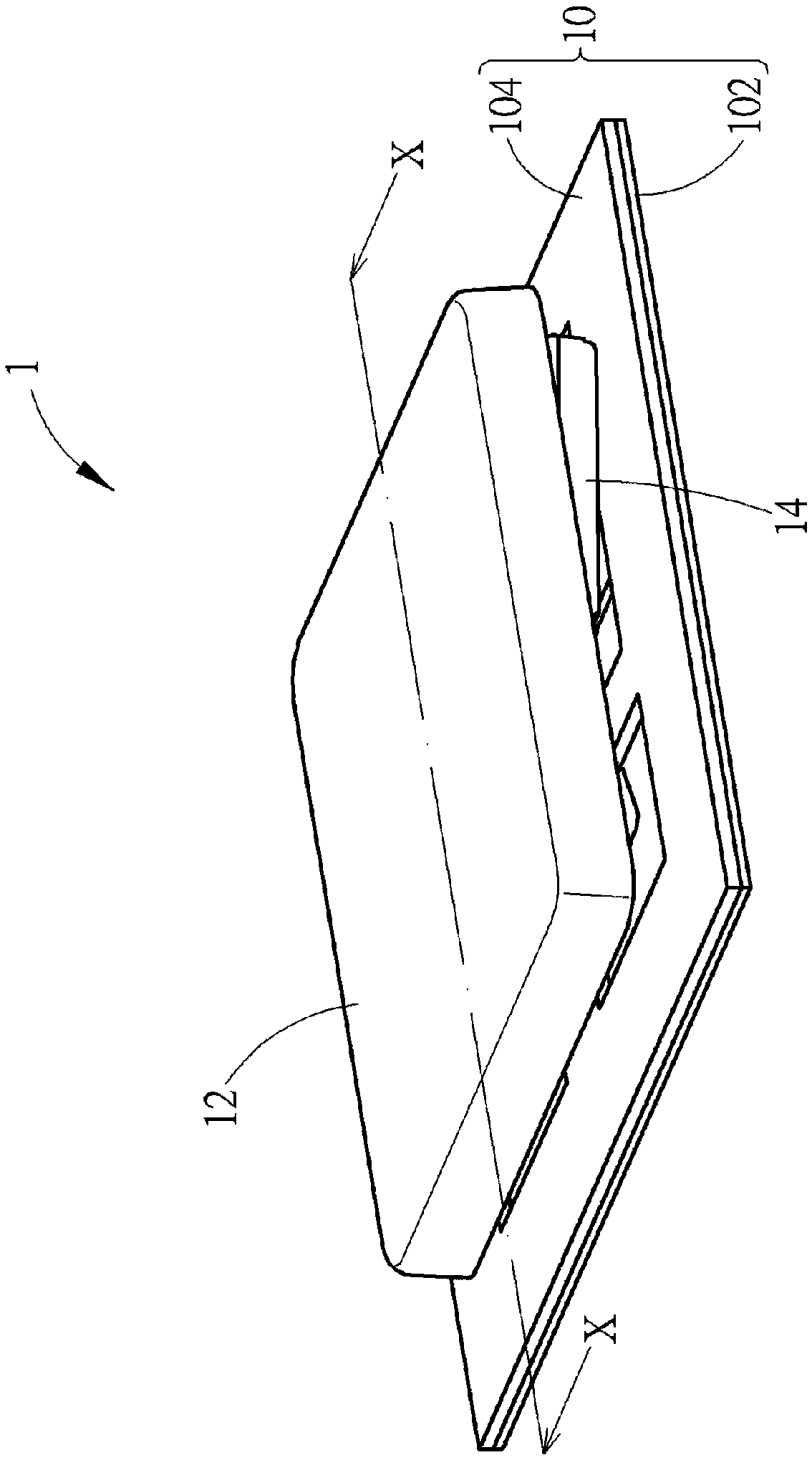
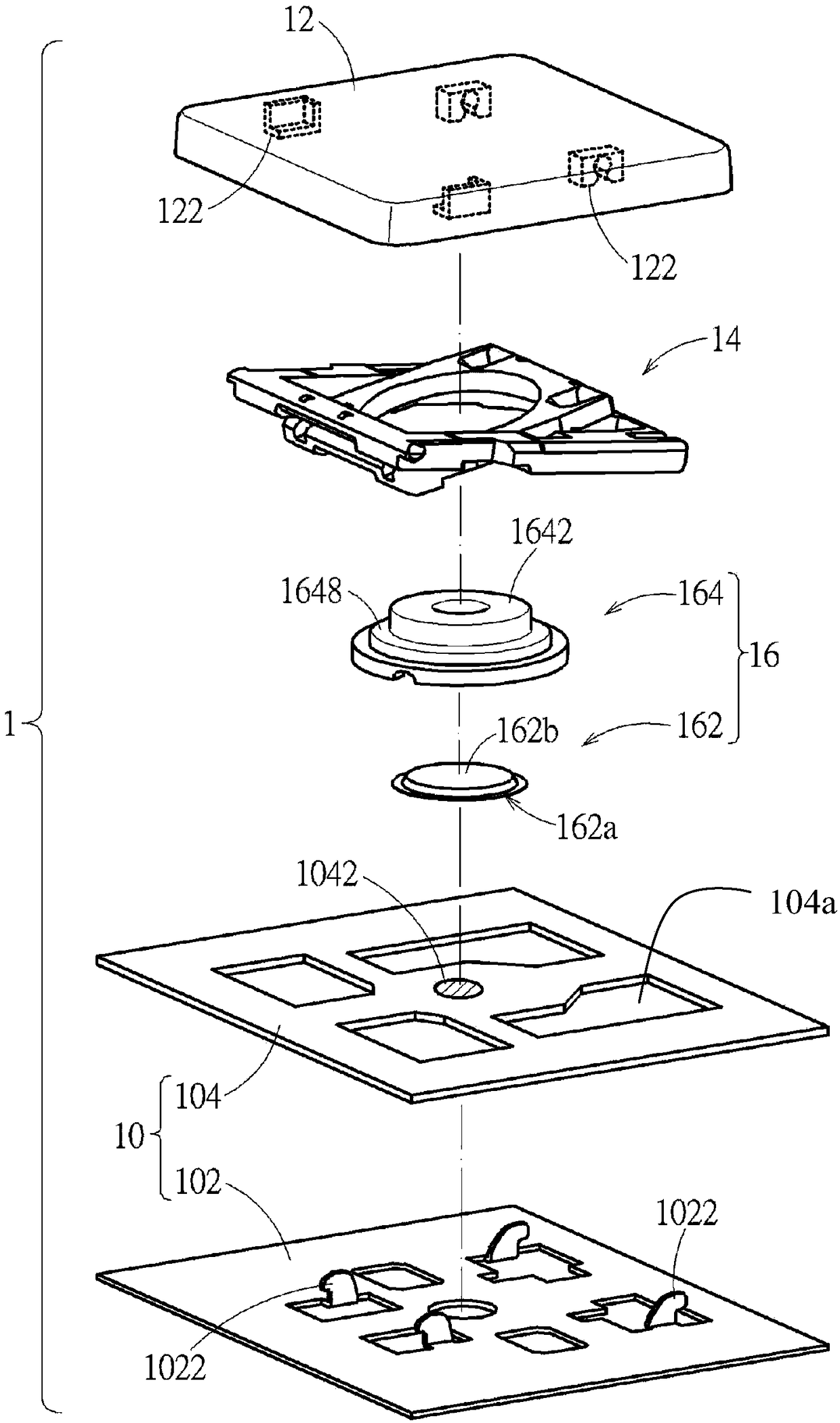
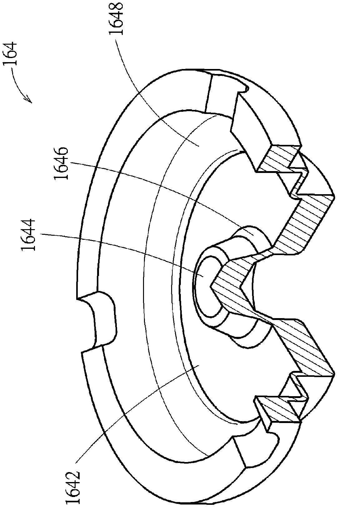
[0039] see Figure 1 to Figure 2 . The button structure 1 according to an embodiment of the present invention includes a base 10 , a keycap 12 , a lifting mechanism 14 (such as but not limited to a scissor leg bracket) and a restoring force mechanism 16 . The keycap 12 is disposed above the base 10 . The lifting mechanism 14 is connected between the keycap 12 and the base 10 , so that the keycap 12 can move (for example, move up and down) relative to the base 10 through the lifting mechanism 14 . The restoring force mechanism 16 is disposed between the base 10 and the keycap 12 for providing the restoring force of the keycap 12 (for returning the pressed keycap 12 to its original position).

[0040] In addition, in this embodiment, the base 10 includes a bottom plate 102 and a thin film circuit board 104 . The bottom plate 102 has a plurality of first connecting structures 1022 , and the bottom plate 102 is connected to the lifting mechanism 14 . The film circuit board 104...


PUM


Abstract

The invention relates to a button structure comprising a base, a keycap and a restoring force mechanism. The restoring force mechanism is arranged between the base and the keycap to provide resilienceto the keycap. The restoring force mechanism comprises a dome-shaped elastic body and an intermediate elastic member. The dome-shaped elastic body is arranged above a switch of the base, and the intermediate elastic member is arranged between the dome-shaped elastic body and the keycap. When the keycap moves toward the base to press the intermediate elastic member, the intermediate elastic memberpresses the dome-shaped elastic body such that the dome-shaped elastic body triggers the switch before the intermediate elastic member elastically bucks. Thereby, the button structure can quickly trigger the switch in response to a pressing operation of the user and can provide the user with sufficient pressing stroke.

Description

technical field [0001] The invention relates to a button structure and its restoring force mechanism, in particular to a button structure and its restoring force mechanism which use elastic bodies to trigger switches and provide pressing restoring force. Background technique [0002] The general button structure is provided with a rubber knob between the keycap and the base, which can be elastically squeezed by the keycap moving downward (ie toward the base) to trigger the corresponding switch, and the elastically deformed rubber knob can provide key The force required for the cap to return to its original position. When the keycap squeezes the rubber knob, the rubber knob is first elastically compressed and deformed, and then elastically buckled to provide the keycap with a pressing stroke. Among them, the rubber knob provides a small part of the pressing stroke of the keycap before the elastic buckling, and the rubber knob uses the elastic buckling to provide a larger par...

Claims


Application Information

Patent Timeline
Patent Type & Authority Applications(China)
IPC IPC(8): H01H13/14H01H13/26
CPCH01H13/14H01H13/26
Inventor 简志鸿赵令溪
Owner DARFON ELECTRONICS (SUZHOU) CO LTD
Learn More