
A fixing structure of an insulated wire and an assembly method thereof

A fixed structure, insulated wire technology, applied in the direction of electrical components, connections, circuits, etc., can solve the problems of not being well protected at the connection of insulated wires, not being able to dissipate heat, and difficult to connect insulated wires.

Active Publication Date: 2019-10-18
安徽德意达铝业有限公司
View PDF6 Cites 0 Cited by
  • Summary
  • Abstract
  • Description
  • Claims
  • Application Information

AI Technical Summary

Problems solved by technology

[0003] A large number of insulated wires are needed to connect the various components in the high-voltage and low-voltage complete sets of equipment. The joints of the insulated wires are often not well protected. The connection of the insulated wires is difficult, and the connection cannot be well protected Heat dissipation, for this reason, we propose a fixed structure of insulated wires and its assembly method to solve the problems mentioned in the above-mentioned background technology

Method used


Image

  • A fixing structure of an insulated wire and an assembly method thereof
  • A fixing structure of an insulated wire and an assembly method thereof
  • A fixing structure of an insulated wire and an assembly method thereof

Examples


Embodiment Construction

[0023] The following will clearly and completely describe the technical solutions in the embodiments of the present invention with reference to the accompanying drawings in the embodiments of the present invention. Obviously, the described embodiments are only some, not all, embodiments of the present invention. Based on the embodiments of the present invention, all other embodiments obtained by persons of ordinary skill in the art without making creative efforts belong to the protection scope of the present invention.

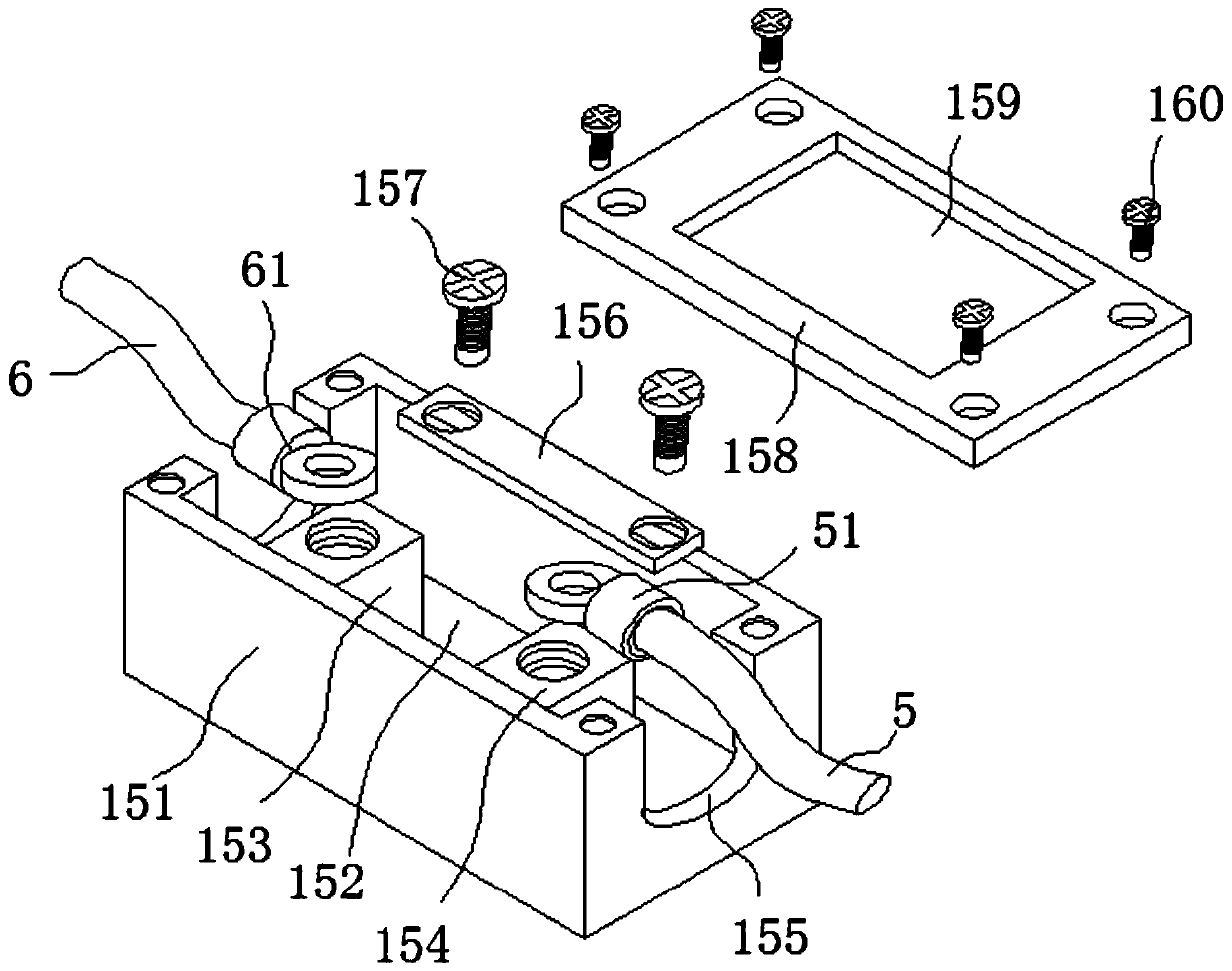
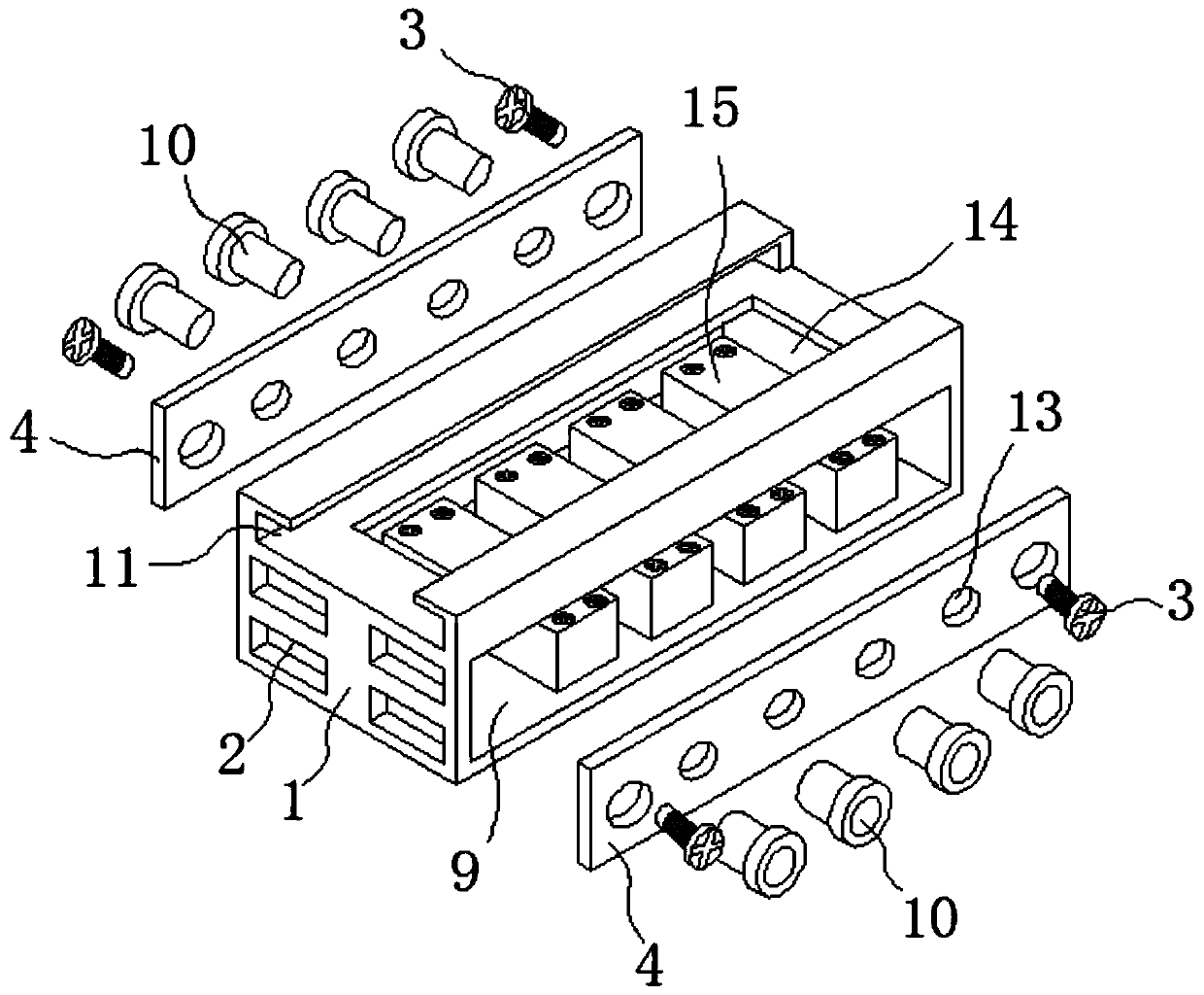
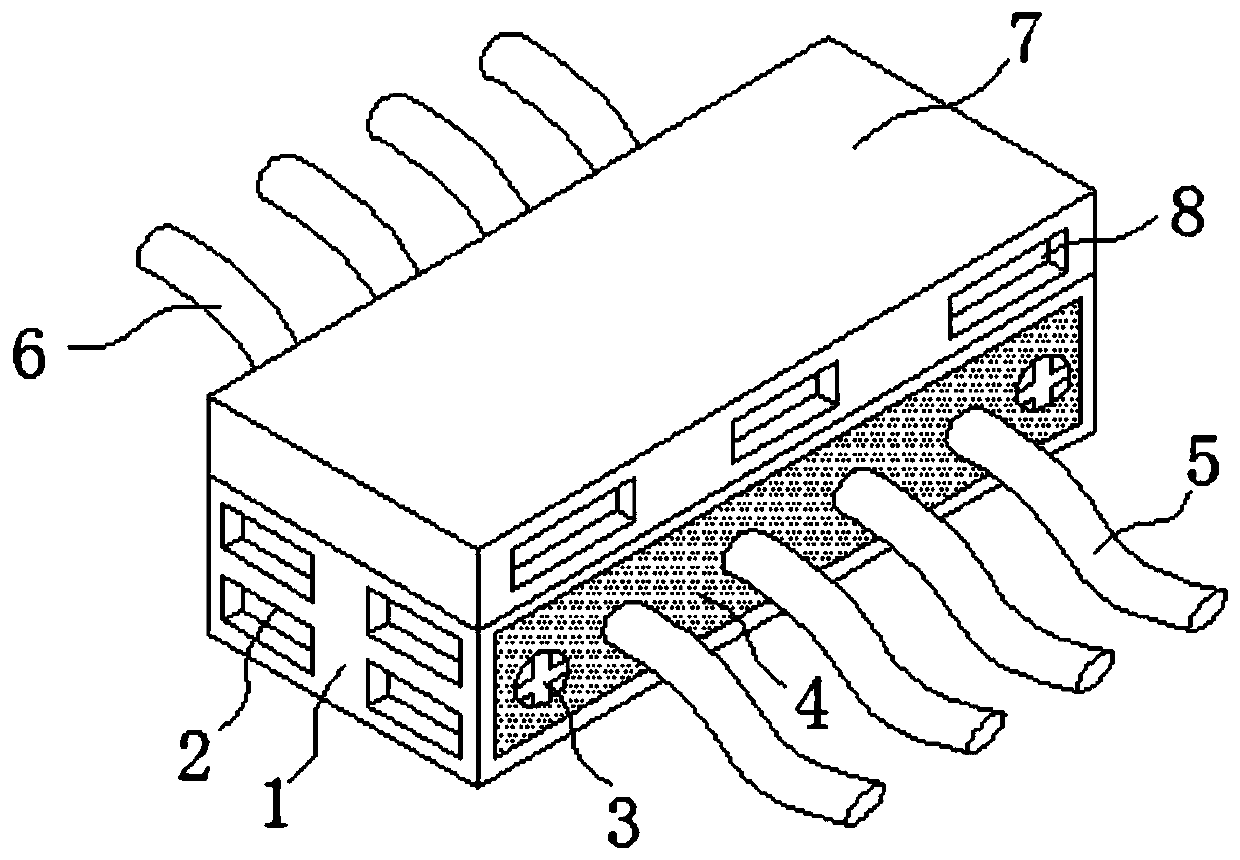
[0024] The present invention provides such Figure 1-4 A fixing structure for an insulated wire, comprising an insulated wire docking seat 1, an end cover 7 is provided on the upper end of the insulated wire docking seat 1, and an air intake opening groove 8 is provided on both sides of the end cover 7, and the end The lower end of cover 7 is provided with groove 72, and cooling fan 12 is installed in described groove 72, and the upper middle part of describe...


PUM


Abstract

The invention discloses a fixation structure of insulated wires. The fixation structure comprises a butt-joint seat of the insulated wires, an end cap is arranged in the upper end of the butt-joint seat of the insulated wires, air inlet open slots are arranged at the two sides of the end cap respectively, a groove is arranged in the lower end of the end cap, heat-radiation fans are installed in the groove, the two sides of the butt-joint seat of the insulated wires are respectively provided with wire-through open slots through which the insulated wires penetrate, each wire-through open slot isinternally provided with a protection plate, the upper end of a rectangular casing is provided with a rectangular groove, the rectangular groove is internally provided with first and second ceramic terminals in symmetry, and a metal connection plate is connected with the first and second insulted wires between the first and second ceramic terminals. Due to arrangement of the butt-joint seat and ajunction box, positions where the insulated wires are connected with the first and second terminals and the metal connection plate are protected, and danger caused by person contact when the insulated wires are powered on is avoided.

Description

technical field [0001] The invention belongs to the technical field of hoisting and fixing structures for insulated wires, and in particular relates to a fixing structure for insulated wires, and also relates to an assembly method for the fixing structure for insulated wires. Background technique [0002] Evenly and tightly wrap a layer of non-conductive material on the periphery of the wire, such as: resin, plastic, silicone rubber, PVC, etc., to form an insulating layer to prevent the conductor from contacting the outside world to cause leakage, short circuit, electric shock and other accidents. The wire is called insulation. wire. [0003] A large number of insulated wires are needed to connect the various components in the high-voltage and low-voltage complete sets of equipment. The joints of the insulated wires are often not well protected. The connection of the insulated wires is difficult, and the connection cannot be well protected For heat dissipation, we propose a...

Claims


Application Information

Patent Timeline
Patent Type & Authority Patents(China)
IPC IPC(8): H01R9/24
Inventor 李龙龙马书龙
Owner 安徽德意达铝业有限公司
Learn More