Supercharge Your Innovation With Domain-Expert AI Agents!

Locking device

A technology of locking devices and locking parts, which is applied in the direction of coupling devices, components of connecting devices, electrical components, etc., can solve the problems of poor operation, few locking devices, and high structural strength, and achieve the effect of convenient operation

Active Publication Date: 2018-08-24
DEYI PRECISION ELECTRONIC IND CO LTD PANYU
View PDF5 Cites 1 Cited by
  • Summary
  • Abstract
  • Description
  • Claims
  • Application Information

AI Technical Summary

Problems solved by technology

[0003] In order to hold the electronic card, the existing electrical connector assembly is equipped with locking devices on both sides of the insulating body. The existing locking devices are generally made of plastic materials, and the strength of the locking devices made of plastic is relatively small. The lock device is easy to wear or break, and cannot work normally; at present, there are also lock devices made of metal on the market. The purpose of the card, but when inserting or removing the metal lock device, one hand must pull the metal lock device to make it elastically deformed, and at the same time the other hand inserts or removes the card, but inserting or removing the card The card process is not easy to operate with one hand, so the metal lock device is rarely used

Method used


Image

  • Locking device
  • Locking device
  • Locking device

Examples


Embodiment Construction

[0037] In order to facilitate a better understanding of the purpose, structure, features, and effects of the present invention, the present invention will now be further described in conjunction with the accompanying drawings and specific embodiments.

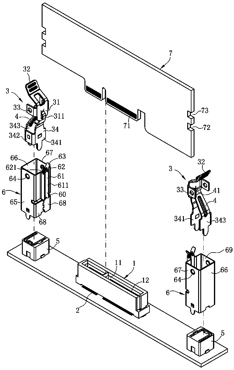
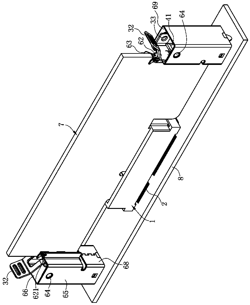
[0038] like figure 1 As shown, the present invention provides a locking device for locking an electronic card 7, the electronic card 7 is electrically connected to an electrical connector, and the electrical connector is fixed to a circuit board 8, including : a locking part 3 and a fixing part 6.

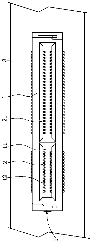
[0039] like figure 1 and image 3 As shown, the electrical connector includes an insulating body 1 installed on the circuit board 8, the insulating body 1 extends along the longitudinal direction, and the insulating body 1 is recessed along the longitudinal direction to accommodate the electronic A central slot 11 of the card 7 , a plurality of terminal slots 12 are located on one side of the central slot 11 and communicate with ...


PUM


Abstract

The invention discloses a locking device for locking an electronic card having at least one groove. The locking device comprises a locking component having a main part and a pulling part, wherein themain part has a buckle portion and a first retaining portion extending from the main part, the buckle portion is used for locking to the groove; and a fixing member having a second retaining portion,wherein the first retaining portion is located at the second retaining portion when the buckle portion is separated from the groove by the pulling part. According to the locking device, the first retaining portion is disposed on the locking component, and firstly the pulling part is pulled by one hand to locate the first retaining portion at the second retaining portion on the fixing member in order that the buckle portion is disengaged from the groove, and then the hand can leave the pulling part, and the electronic card can be further removed by both hands. The locking device is convenient to operate.

Description

technical field [0001] The invention relates to a locking device, in particular to an electronic card locking device. Background technique [0002] The existing electrical connector assembly for inserting an electronic card includes an insulating body fixed on a circuit board. The insulating body is provided with a central slot along the longitudinal direction, and two sides of the central slot are provided with the central slot. A plurality of terminal slots connected by slots, a plurality of conductive terminals are respectively accommodated in a plurality of the terminal slots, each of the conductive terminals has a contact portion exposed in the central slot for electrical connection with the electronic card Leading part docking. [0003] In order to hold the electronic card, the existing electrical connector assembly is equipped with locking devices on both sides of the insulating body. The existing locking devices are generally made of plastic materials, and the stren...

Claims


Application Information

Patent Timeline
Patent Type & Authority Applications(China)
IPC IPC(8): H01R12/70H01R13/639
CPCH01R12/7011H01R12/7064H01R13/639
Inventor 彭治国何菲
Owner DEYI PRECISION ELECTRONIC IND CO LTD PANYU
Features
  • R&D
  • Intellectual Property
  • Life Sciences
  • Materials
  • Tech Scout
  • Unparalleled Data Quality
  • Higher Quality Content
  • 60% Fewer Hallucinations
Learn More