
Vehicle tail lamp control system and control method thereof

A technology for automobile taillights and control systems, which is applied to lighting devices, light sources, electrical components, etc., can solve the problem of not being able to judge the motion state of the vehicle, and achieve the effect of ensuring safety.

Inactive Publication Date: 2018-08-24
浙江福林国润汽车零部件有限公司 +1
View PDF6 Cites 2 Cited by
  • Summary
  • Abstract
  • Description
  • Claims
  • Application Information

AI Technical Summary

Problems solved by technology

The disadvantage of this invention is that the brightness of the taillights is adjusted through the associated action of the taillights and horns, so as to warn the vehicles coming from behind more visually, but it cannot be judged according to the situation of the taillights. exercise state

Method used


Image

  • Vehicle tail lamp control system and control method thereof
  • Vehicle tail lamp control system and control method thereof

Examples


Embodiment Construction

[0026] The present invention will be further described below in conjunction with the accompanying drawings and specific embodiments.

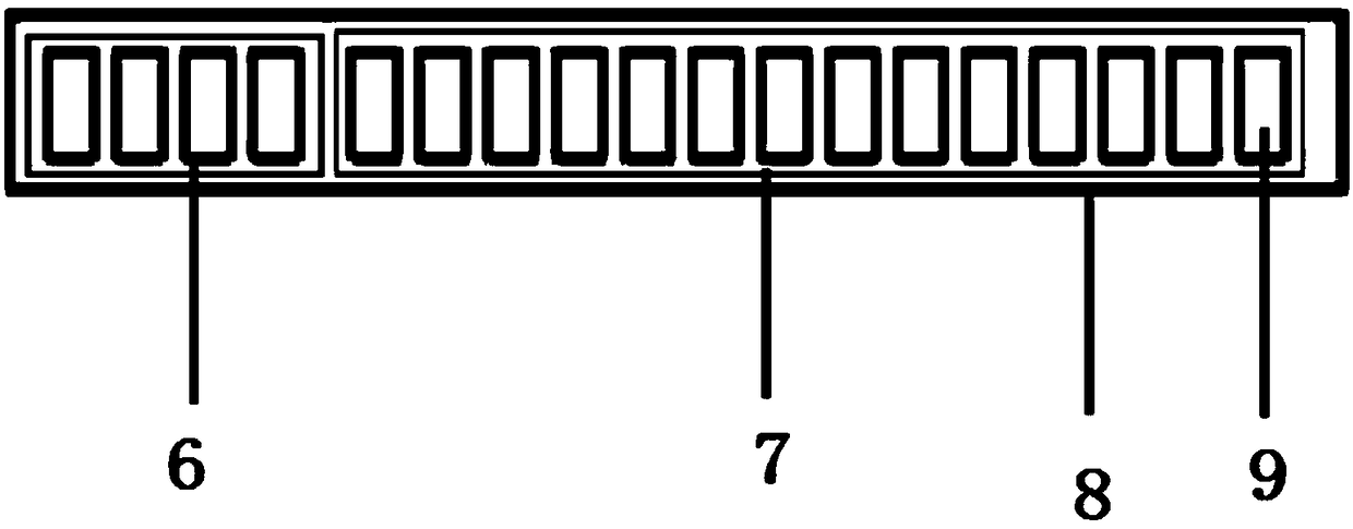
[0027] Such as figure 1 In the described embodiment, a vehicle taillight control system includes a speed sensor 5 for detecting vehicle speed, a brake sensor 1 for detecting braking force, and a controller for processing the signals of the speed sensor 5 and the signal of the brake sensor 1 2. The execution circuit 3 and the taillight 4 of the automobile, the speed sensor 5 , the brake sensor 1 and the execution circuit 3 are all connected to the controller 2 , and the execution circuit 3 is connected to the taillight 4 of the automobile. The automobile taillight 4 is a strip light strip 8, and the strip light strip 8 is composed of several LED lights 9.

[0028] Based on a control method for the control system of the automobile taillight 4, the output state of the automobile taillight 4 is controlled by the controller 2, thereby judging the b...


PUM


Abstract

The invention discloses a vehicle tail lamp control system and a control method thereof. The device comprises a speed sensor used for detecting the speed of a vehicle, a brake sensor used for detecting the brake force, a controller used for processing the signal of the speed sensor and the signal of the brake sensor, an execution circuit and a vehicle tail lamp. The speed sensor, the brake sensorand the execution circuit are both connected with the controller. The execution circuit is connected with the vehicle tail lamp. The invention has the beneficial effects that the brake force can be distinguished differently. The condition that people and vehicles behind a vehicle are greatly influenced by the slow speed or the high brightness of the vehicle tail lamp of the current vehicle duringparking can be avoided. The vehicle tail lamp can be changed to be diversified in state according to different driving speeds of the vehicle. As a result, the safety of people and vehicles behind thevehicle can be ensured.

Description

technical field [0001] The invention relates to the related technical field of automobile parts, in particular to an automobile taillight control system and a control method thereof. Background technique [0002] Now the traditional braking system is to turn on the brake switch by depressing the brake pedal by the driver to make the brake tail lights light up. The disadvantage of this structure is that no matter whether the driver steps on the brake pedal lightly or heavily, that is, the driver wants to slow down or brake suddenly, the brake tail lights of the car will light up, and there is no difference in brightness and color. Because the vehicle is in the process of driving, with the speed of the vehicle changing and the quality of the driver itself, the driver of the vehicle behind will have a misjudgment of the speed. Although the driver of the rear car sees the driver of the car in front stepping on the brakes, it is impossible to judge whether the driver of the car ...

Claims


Application Information

Patent Timeline
Patent Type & Authority Applications(China)
IPC IPC(8): H05B33/08H05B44/00
CPCH05B45/00
Inventor 汪小敏
Owner 浙江福林国润汽车零部件有限公司
Learn More