
Supercritical CO2 fluid foaming machine

A supercritical and foamer technology, applied in the field of foaming, can solve the problems that researchers are difficult to obtain the expected experimental results, the air tightness of the device is weakened, and the support frame is difficult to balance, so as to achieve reasonable distribution and fixed stability of the temperature measuring device The effect of improving, accurate and effective measurement

Active Publication Date: 2018-08-28
HANGZHOU DIANZI UNIV
View PDF5 Cites 0 Cited by
  • Summary
  • Abstract
  • Description
  • Claims
  • Application Information

AI Technical Summary

Problems solved by technology

[0004] 1. The temperature is unevenly heated. Some foaming experiments require heating with an oil bath, and some require heating with a heating tube. Therefore, when the experimental requirements are different, a single heating design and a device lacking a stirrer will make it difficult for researchers to obtain the expected experimental results.
[0005] 2. The airtightness is low, and the support frame is difficult to balance. First, in the traditional device, the material bracket is connected to the autoclave or supported at the bottom of the autoclave, which easily causes problems such as unstable support and low experimental efficiency.
Second, if the exhaust valve adopts a traditional valve, it will easily weaken the airtightness of the device under the condition of high pressure

Method used


Image

  • Supercritical CO2 fluid foaming machine
  • Supercritical CO2 fluid foaming machine
  • Supercritical CO2 fluid foaming machine

Examples


Embodiment Construction

[0065] The following are specific embodiments of the invention and in conjunction with the accompanying drawings, the technical solutions of the present invention are further described, but the present invention is not limited to these embodiments.

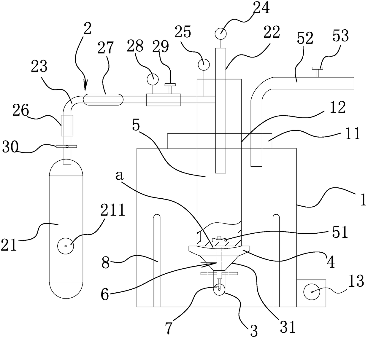
[0066] Such as figure 1 As shown, the supercritical CO 2 The fluid foamer includes a sealed cylinder 1, a pressurizing device 2, and a heating medium stored in the sealed cylinder 1, and the heating medium is oil.

[0067] An insulation layer is arranged on the inner wall of the sealed cylinder.

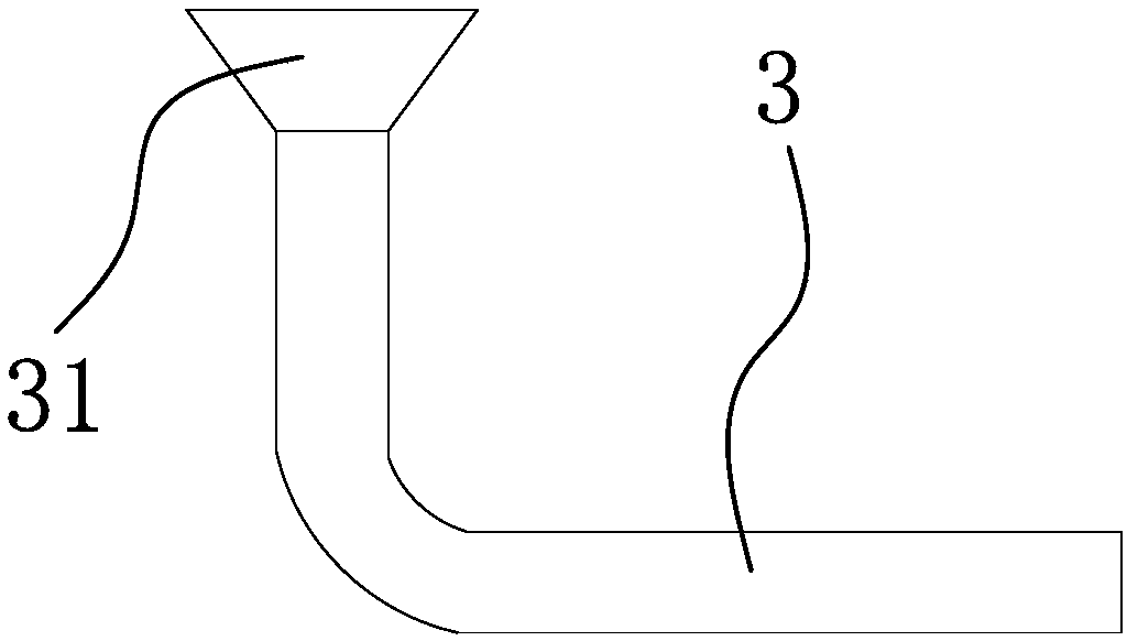
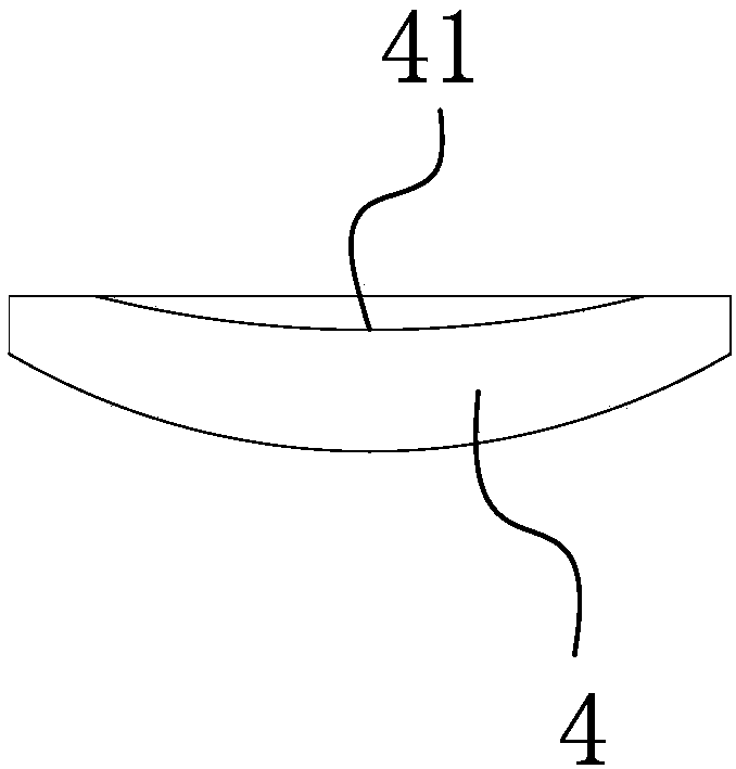
[0068] Such as Figure 1-2 As shown, a cantilever support tube 3 is connected to the inner wall of the sealed cylinder body 1, and the cantilever support tube 3 is in an L-shaped structure. The cantilever support tube 3 includes a horizontal section and a vertical section connected with the horizontal section. The segment axis coincides with the axis of the sealed cylinder 1.

[0069] One end of the horizontal section away from the v...


PUM


Abstract

The invention relates to a supercritical CO2 fluid foaming machine and a foaming method thereof, and solves the technical problems of unreasonable design and the like in the prior art. The supercritical CO2 fluid foaming machine comprises a sealed cylinder body and a pressurizing device, and a heating medium stored in the sealed cylinder body, wherein the inner wall of the sealed cylinder body isconnected with a cantilever type supporting pipe; the suspended end of the cantilever type supporting pipe is connected with a horizontally arranged arc-shaped tray; a high-pressure kettle is arrangedon the arc-shaped tray, and a sealed cavity is formed between the upper surface of the arc-shaped tray and the bottom of the high-pressure kettle; the upper end of the high-pressure kettle upwards penetrates out, reaches the top of the sealed cylinder body and is connected with the pressurizing device; an agitating device located below the arc-shaped tray is also arranged at the suspended end ofthe cantilever type supporting pipe; the agitating device is connected with a power supply line penetrating into the cantilever type supporting pipe; a plurality of heating pipes distributed in the circumferential direction of the high-pressure kettle are also arranged in the sealed cylinder body; a supporting frame is arranged at the inner bottom of the high-pressure kettle. The supercritical CO2fluid foaming machine has the advantage of improving the foaming quality.

Description

technical field [0001] The invention belongs to the technical field of foaming, in particular to a supercritical CO 2 Fluid bubbler. Background technique [0002] Supercritical CO 2 The foaming device is a crucial device for the preparation of polymer porous materials. The experimental equipment is mainly composed of four parts: pressurization device, autoclave, heating device and pressure relief device. The preparation of different polymers has different requirements and conditions for the equipment. [0003] Traditional supercritical CO 2 There are mainly the following problems in the preparation of polymer porous materials by foaming devices: [0004] 1. The temperature is unevenly heated. Some foaming experiments require heating with an oil bath, and some require heating with a heating tube. Therefore, when the experimental requirements are different, a single heating design and a device lacking a stirrer will make it difficult for researchers to obtain the expected...

Claims


Application Information

Patent Timeline
Patent Type & Authority Applications(China)
IPC IPC(8): B29C44/34
CPCB29C44/3403B29C44/3415B29C44/35
Inventor 鄢腊梅钟榆星袁友伟
Owner HANGZHOU DIANZI UNIV
Learn More