Power distribution station motor stator core fixing device

A stator core and fixing device technology, applied in the manufacture of the stator/rotor body, etc., can solve the problems of inconvenient fixing, poor replacement, vibration, etc., and achieve the advantages of convenient and quick adjustment of the fixed height, high fixing firmness, and improved stability Effect

Active Publication Date: 2017-02-15
潘学勇
View PDF6 Cites 5 Cited by
  • Summary
  • Abstract
  • Description
  • Claims
  • Application Information

AI Technical Summary

Problems solved by technology

[0003] The motor is generally composed of end cover, stator, outlet box, position speed sensor and fan, etc. The stator mainly includes the machine base, stator core and winding, and the rotor mainly includes the shaft, rotor core and magnetic steel; the manufacturing process of the motor includes The machining process of parts, the manufacturing process of the iron core, the manufacturing process of the winding, the manufacturing process of the rotor and the motor assembly process; the most important step in the manufacturing process of the iron core is the cleaning of the iron core. When cleaning the motor stator core, it is necessary to The stator core of the motor is fixed. At present, the main problem is that it is inconvenient to fix. More, in view of this, the present invention provides a stator core fixing device for substation motors

Method used


Image

  • Power distribution station motor stator core fixing device
  • Power distribution station motor stator core fixing device
  • Power distribution station motor stator core fixing device

Examples


Embodiment Construction

[0017] In order to make the technical means, creative features, goals and effects achieved by the present invention easy to understand, the present invention will be further described below in conjunction with specific illustrations.

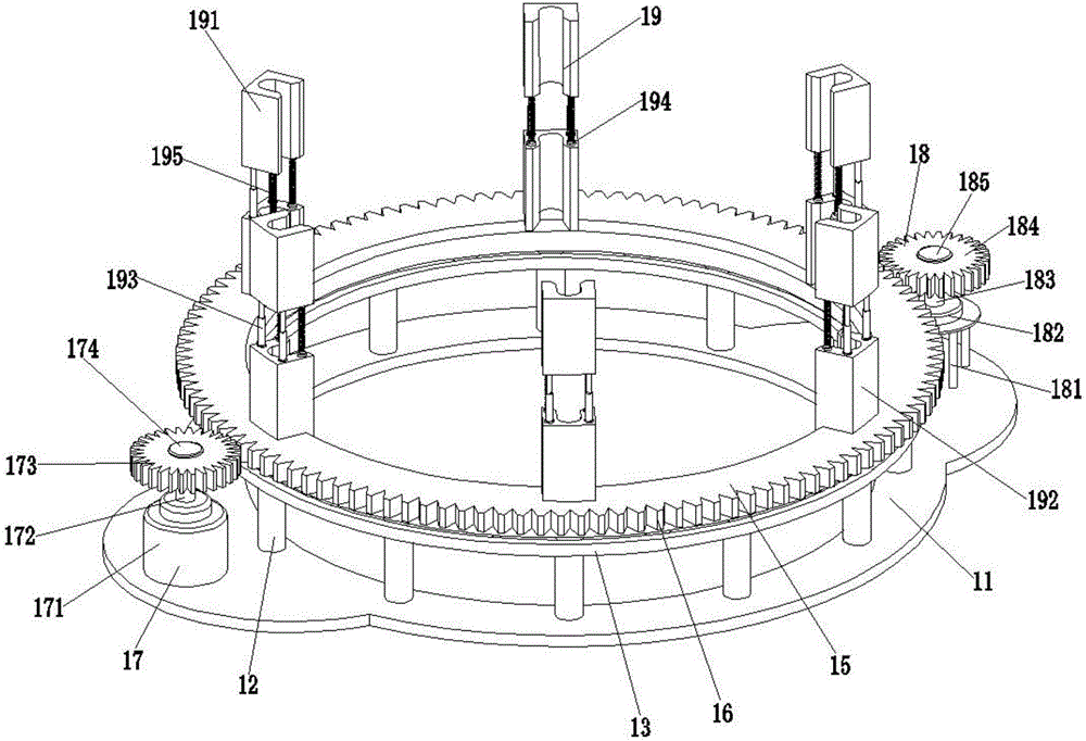
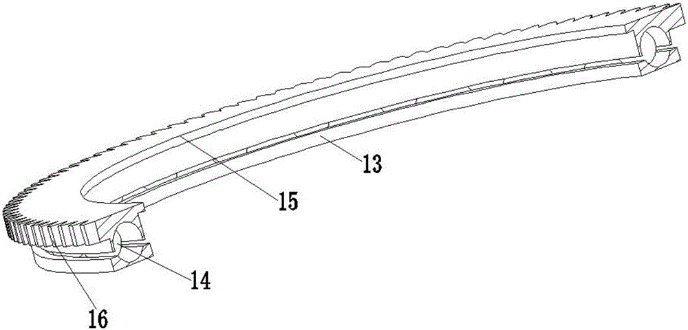
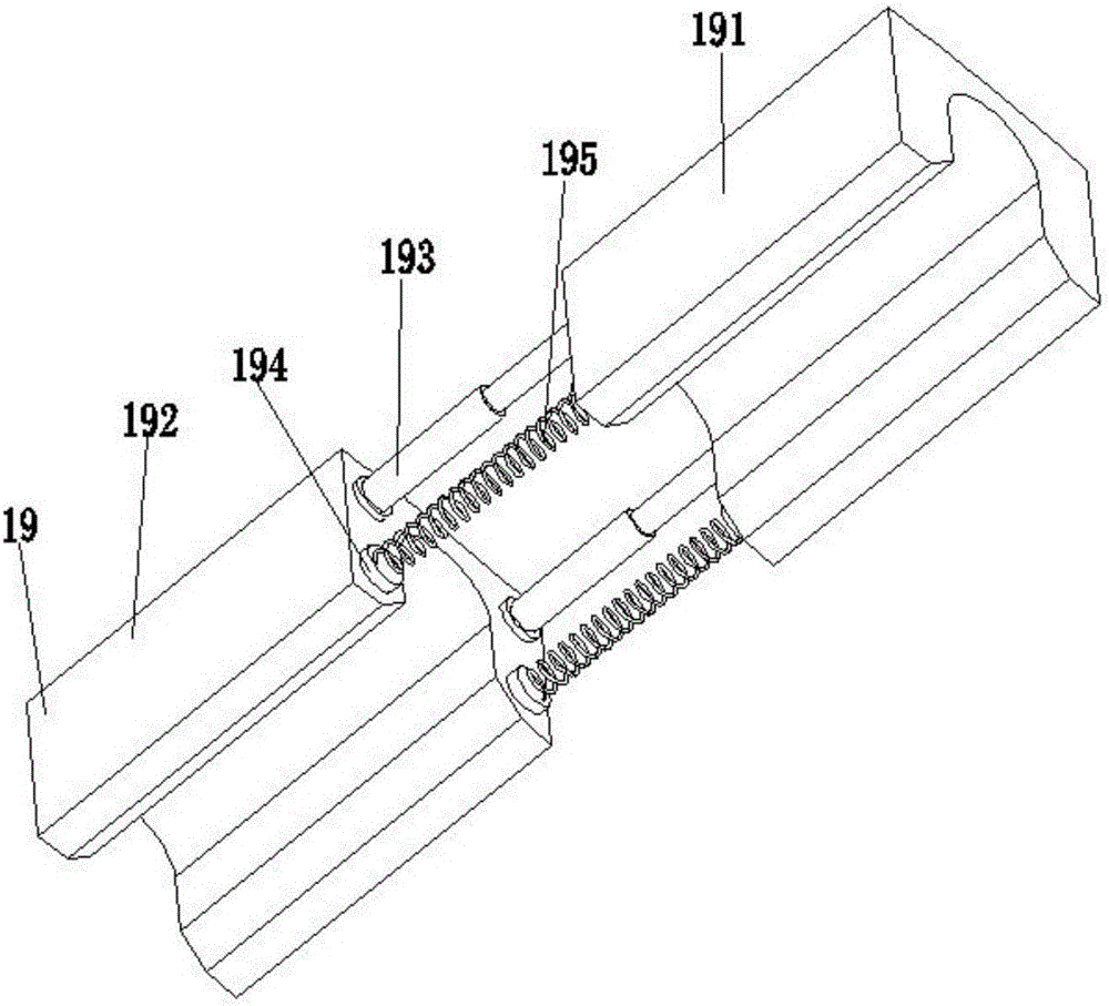
[0018] Such as Figure 1 to Figure 3 As shown, a stator core fixing device for a substation motor includes a chassis base 11, a support rod 12, a ring guide rail 13, a rotating ball 14, a rotating disk 15, a driven gear 16, a power output mechanism 17, and a limit mechanism 18 and support fixing mechanism 19; the middle part of the chassis seat 11 is provided with a chip leakage hole, and the left and right sides of the chassis seat 11 are respectively symmetrically provided with semicircular convex seats, and the support rod 12 is located between the chassis seat 11 and the annular guide rail 13, and The support rods 12 are arranged at equal intervals along the circumferential direction of the chip leakage hole edge on the chassis base 11, the ...


PUM


Abstract

The invention relates to a power distribution station motor stator core fixing device, including a chassis seat, a support rod, an annular guide rail, a rotary ball, a rotary disk, a driven gear, a power output mechanism, a limiting mechanism and a support fixing mechanism. The support rod is located between the chassis seat and the annular guide rail, the upper part of the rotary ball sleeves an annular groove on a bottom end face of the rotary disk, the lower part of the rotary ball is mounted in an annular guide groove on an upper end face of the annular guide rail, the driven gear is fixed on an outer side wall of the rotary disk, the power output mechanism is located at the left side of the driven gear, the limiting mechanism is located at the right side of the driven gear, and the support fixing mechanism is located right above the rotary disk. The power distribution station motor stator core fixing device provided by the invention can perform motion in space in directions of two degrees of freedom including translation and rotation, and thus can adjust the fixed height and position in a circumferential direction of a motor stator core, during adjustment of the position in the circumferential direction, friction force is small, the function of fixing the motor stator core is realized, the fixing firmness is high, and the stability is high.

Description

technical field [0001] The invention relates to the field of electric motor auxiliary machinery, in particular to a stator iron core fixing device for a substation motor. Background technique [0002] The distribution station is a place to change the voltage. In order to transmit the electric energy from the power plant to a distant place, the voltage must be raised and turned into high-voltage electricity, and the voltage must be lowered as needed near the user. The work of the distribution station is completed by the distribution station; the main equipment of the distribution station is a switch and a transformer, but there are also some electric auxiliary equipment. The motors are all large, depending on the size, the small ones are called substations, and the substations are larger than the substations; substations: generally step-down substations with a voltage level below 110KV; substations: including various voltage levels "Boost, step-down" substation. [0003] Th...

Claims


Application Information

Patent Timeline
Patent Type & Authority Applications(China)
IPC IPC(8): H02K15/02
CPCH02K15/02
Inventor 潘学勇
Owner 潘学勇
Why Eureka
Try Eureka