
Internet-based remote monitoring device

A remote monitoring device and Internet technology, applied in the Internet field, to achieve the effect of monitoring without dead ends

Inactive Publication Date: 2018-08-28
佛山市聚成知识产权服务有限公司
View PDF11 Cites 0 Cited by
  • Summary
  • Abstract
  • Description
  • Claims
  • Application Information

AI Technical Summary

Problems solved by technology

[0004] The purpose of the present invention is to provide a remote monitoring device based on the Internet, to solve the existing technical defects and unreachable technical requirements

Method used

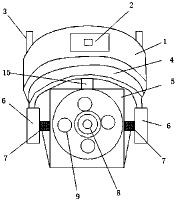
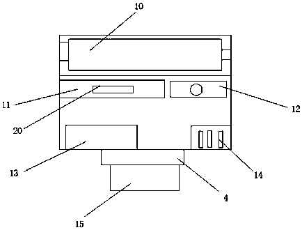

Image

  • Internet-based remote monitoring device
  • Internet-based remote monitoring device
  • Internet-based remote monitoring device

Examples


Embodiment Construction

[0018] The following will clearly and completely describe the technical solutions in the embodiments of the present invention with reference to the accompanying drawings in the embodiments of the present invention. Obviously, the described embodiments are only some, not all, embodiments of the present invention. Based on the embodiments of the present invention, all other embodiments obtained by persons of ordinary skill in the art without making creative efforts belong to the protection scope of the present invention.

[0019] see Figure 1-3 , the present invention provides a technical solution: an Internet-based remote monitoring device, including a machine box 1, a power port 2, a bolt 3, a rotating rod 4, a monitor 5, a mount 6, a lens 8, a night vision device 9, Server 17, signal receiving module 18, described machine box 1 surface is provided with power supply port 2, and described machine box 1 top is provided with bolt 3, and bolt 3 is connected with machine box 1 by ...


PUM


Abstract

The invention discloses an Internet-based remote monitoring device, and the Internet-based remote monitoring device comprises a machine box, a power port, a bolt, a rotating rod, a monitor, a mountingbase, a lens, a night vision device and a server, wherein two sides of the bottom of the machine box are provided with the mounting base, an inner side of the mounting base is provided with the monitor, the top of a connection rod is provided with the rotating rod, a middle side on the surface of the monitor is provided with the lens, and a power supply device, a CPU, a motor, a converter and anintelligent chip are arranged at the inside of the machine box. For the Internet-based remote monitoring device, a signal booster and the motor are arranged on equipment, the monitoring device cannotcause imaging blurring and delay of Internet monitoring equipment due to signal interference, monitoring video records can be provided accurately in real time, a monitor of the monitoring device can realize all-around monitoring area and has no blind area of field of view. The Internet-based remote monitoring device is low in structure cost and easy to generalize and use.

Description

technical field [0001] The invention relates to the technical field of the Internet, in particular to an Internet-based remote monitoring device. Background technique [0002] The Internet (English: Internet), also known as the Internet, or the transliteration of the Internet (Internet), the Internet, the Internet began in 1969 in the United States of America's Arpanet. It is a huge network connected in series between networks. These networks are connected by a set of common protocols to form a logically single huge international network. Generally, the internet generally refers to the Internet, while the Internet refers to the Internet in particular. This method of interconnecting computer networks can be called "network interconnection". On this basis, a global Internet covering the whole world is developed called the Internet, which is a network structure that is interconnected. The Internet is not the same as the World Wide Web. The World Wide Web is just a global syst...

Claims


Application Information

Patent Timeline
Patent Type & Authority Applications(China)
IPC IPC(8): H04N7/18H04N5/76H04N5/232H04N5/225H04B7/155
CPCH04B7/15535H04N5/76H04N7/18H04N23/54H04N23/66H04N23/60
Inventor 赵贵梅
Owner 佛山市聚成知识产权服务有限公司
Learn More