
Welder

A welding machine and driving motor technology, applied in welding equipment, auxiliary welding equipment, welding/cutting auxiliary equipment, etc., can solve problems such as affecting the use of pipe fittings, misalignment of the welding of two sections of pipe fittings, affecting welding quality, etc., and achieve a reasonable design. Effect

Inactive Publication Date: 2018-08-31
JIANGSU MARITIME INST
View PDF0 Cites 0 Cited by
  • Summary
  • Abstract
  • Description
  • Claims
  • Application Information

AI Technical Summary

Problems solved by technology

[0003] However, when it comes to the welding of two sections of pipe fittings, it is necessary to clamp and fix the two sections of pipe fittings reasonably and effectively, otherwise it may cause misalignment of the welding points of the two sections of pipe fittings, which will affect the use of the pipe fittings formed by welding in the later stage, and take into account the size of the pipe fittings to be welded The size of the outer diameter is different, if the height of the welding head is not adjusted, it will also affect the welding quality

Method used


Image

  • Welder
  • Welder

Examples


Embodiment Construction

[0015] The technical solutions in the embodiments of the present invention will be clearly and completely described below in conjunction with the accompanying drawings in the embodiments of the present invention. Obviously, the described embodiments are only a part of the embodiments of the present invention, rather than all the embodiments.

[0016] In the description of the present invention, it should be understood that the terms "upper", "lower", "front", "rear", "left", "right", "top", "bottom", "inner", " The orientation or positional relationship indicated by “outside” is based on the orientation or positional relationship shown in the drawings, and is only for the convenience of describing the present invention and simplifying the description, and does not indicate or imply that the device or element referred to must have a specific orientation to The specific azimuth structure and operation cannot be understood as a limitation of the present invention.

[0017] Such as Fi...


PUM


Abstract

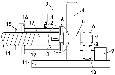
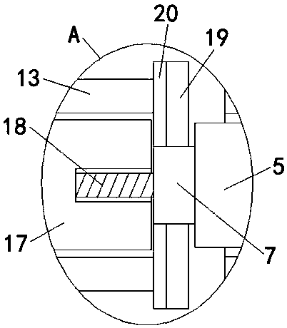
The invention discloses a welder comprising a base. A vertical column is fixedly mounted on the upper surface of the base, a mounting opening is formed in the vertical column, and a bearing is fixedlymounted in the mounting opening. A rotary shaft is rotatably connected into the bearing, a driven wheel is fixedly mounted at one end of the rotary shaft, and a driving motor is fixedly mounted on the upper surface of the base. The driving motor is arranged on the right side of the vertical column, a driving wheel is fixedly mounted at the output end of the driving motor, and the driven wheel andthe driving wheel are connected through a transmission belt. A supporting plate is fixedly mounted on the surface of the side, away from the driving motor, of the vertical column, and an electric telescopic rod is arranged at the bottom of the supporting plate. According to the welder, the design is reasonable, a first connecting pipe tightly abuts against a second connecting pipe through arrangement of a locking sleeve and a limiting block, and through cooperation of the welder and a welding head with the adjustable height, welding forming of a joint of the first connecting pipe and the second connecting pipe can be achieved while a supporting rod rotates.

Description

Technical field [0001] The invention relates to the technical field of welding machines, in particular to a welding machine. Background technique [0002] Welding is the process of joining metal parts with various fusible alloys (solder). The melting point of the solder is lower than that of the material to be welded, so that the part will not be melted, through the intermolecular contact on the surface to complete the welding. [0003] But when it comes to the welding of two sections of pipe fittings, it is necessary to clamp and fix the two sections of pipe fittings reasonably and effectively. Otherwise, the welding places of the two sections of pipe fittings may not be aligned, which will affect the use of the later welded pipe fittings, and take into account the pipe fittings to be welded. The size of the outer diameter is different, if the height of the welding head is not adjusted, the welding quality will also be affected. Summary of the invention [0004] The purpose of th...

Claims


Application Information

Patent Timeline
IPC IPC(8): B23K3/00B23K3/08B23K37/053B23K37/02B23K101/06
CPCB23K3/00B23K3/08B23K3/087B23K37/02B23K37/0533B23K37/0538
Inventor 王艳万廉
Owner JIANGSU MARITIME INST
Learn More