
Printing and dyeing equipment high in printing and dyeing quality

A printing and dyeing equipment and quality technology, which is applied to the equipment configuration of textile materials, the processing of textile materials, textiles and papermaking, etc., can solve the problems such as the inability to adjust the height of the printing and dyeing roller, the inability of the printing and dyeing roller to be in close contact with the material, and the reduction of the printing and dyeing quality of the material. , to achieve the effect of improving stability, reducing friction and improving printing and dyeing quality

Inactive Publication Date: 2018-08-31
叶侃
View PDF0 Cites 5 Cited by
  • Summary
  • Abstract
  • Description
  • Claims
  • Application Information

AI Technical Summary

Problems solved by technology

[0003] The purpose of the present invention is to provide a printing and dyeing equipment with high printing and dyeing quality, which has the advantages of high printing and dyeing quality, and solves the problem that the printing and dyeing equipment uses the printing and dyeing roller to print and dye the material. Since the height of the printing and dyeing roller cannot be adjusted, the printing and dyeing roller cannot be closely connected to the material. contact, thereby reducing the quality of the material printing and dyeing

Method used

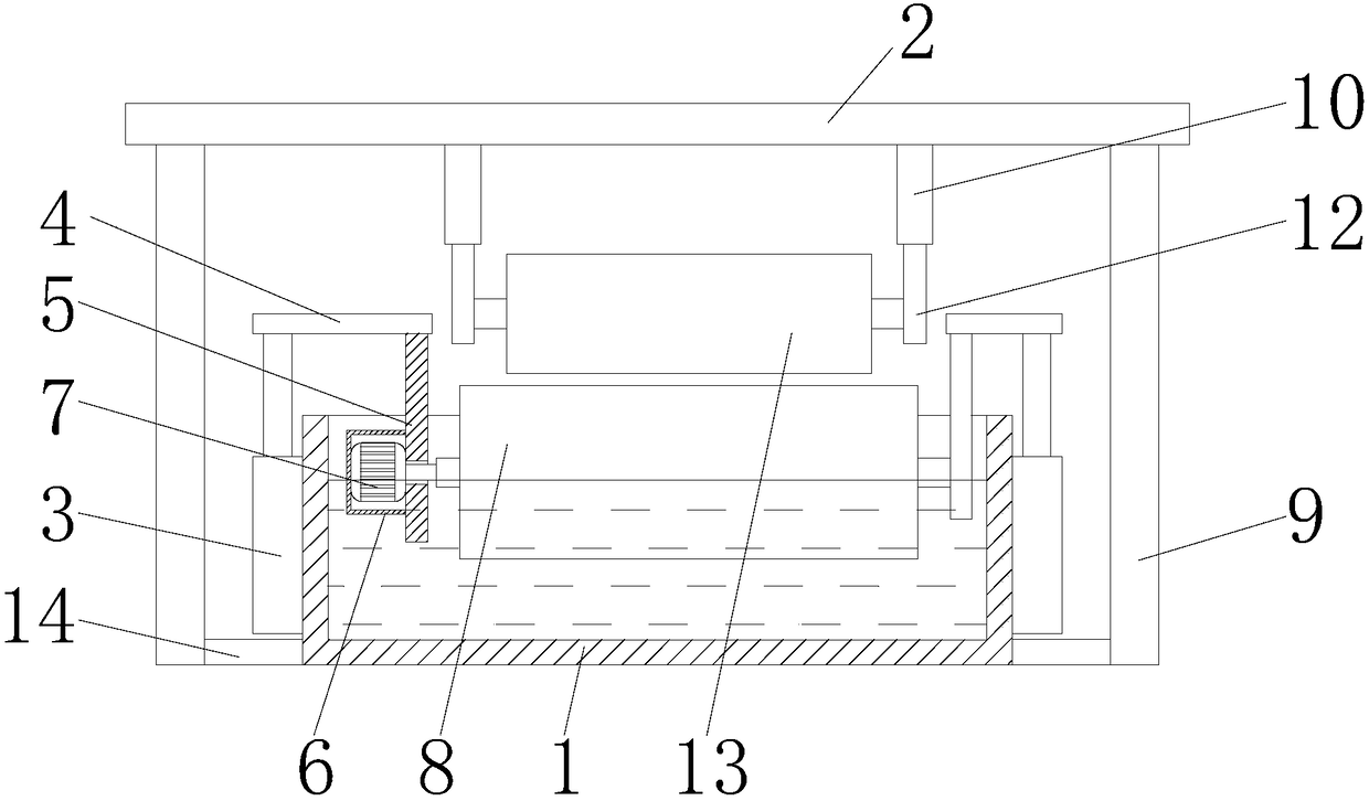
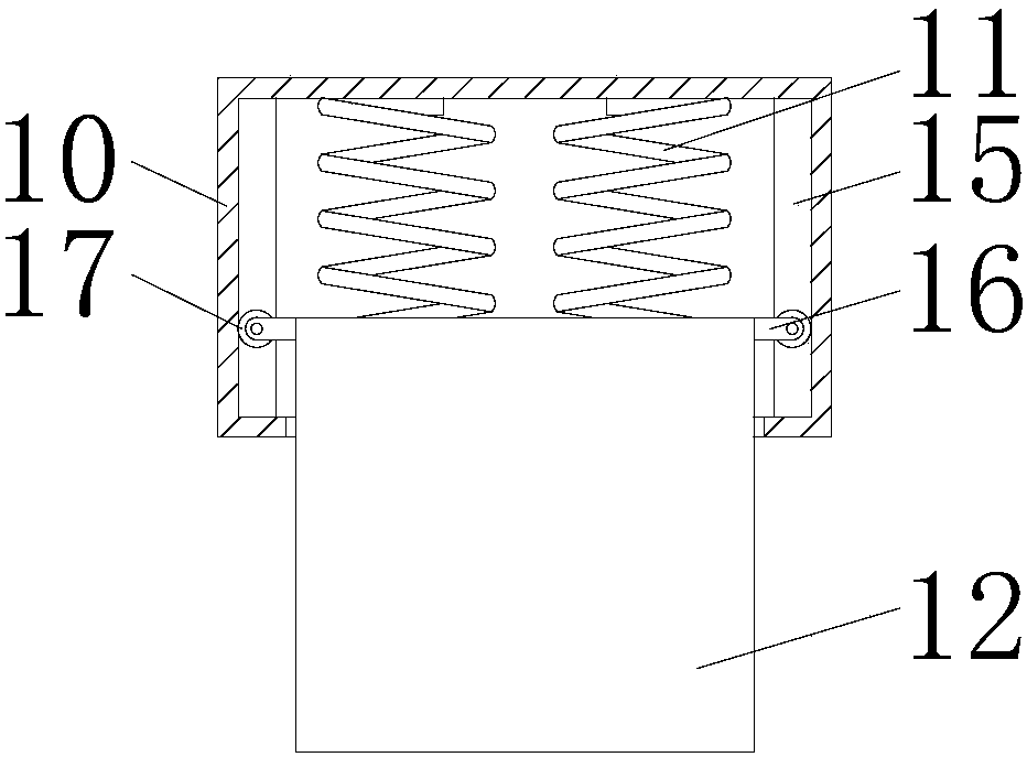

Image

  • Printing and dyeing equipment high in printing and dyeing quality
  • Printing and dyeing equipment high in printing and dyeing quality

Examples


Embodiment Construction

[0014] The following will clearly and completely describe the technical solutions in the embodiments of the present invention with reference to the accompanying drawings in the embodiments of the present invention. Obviously, the described embodiments are only some, not all, embodiments of the present invention. Based on the embodiments of the present invention, all other embodiments obtained by persons of ordinary skill in the art without making creative efforts belong to the protection scope of the present invention.

[0015] see Figure 1-2 , a printing and dyeing equipment with high printing and dyeing quality, comprising a dye box 1 and a horizontal plate 2, the dye box 1 is located below the horizontal plate 2, both sides of the dye box 1 are fixedly connected with electric telescopic rods 3, and the top of the electric telescopic rod 3 A connection plate 4 is fixedly connected, and the bottom of the connection plate 4 is fixedly connected with a riser 5, and the bottom ...


PUM


Abstract

The invention discloses printing and dyeing equipment high in printing and dyeing quality. The equipment comprises a dye box and a transverse plate, the dye box is located below the transverse plate,the two sides of the dye box are both fixedly connected with an electric retractable rod, the top of each electric retractable rod is fixedly connected with a connecting plate, the bottom of each connecting plate is fixedly connected with a vertical plate, and the bottom of each vertical plate extends to an inner cavity of the dye box; a motor box is fixedly connected with the positions, in the inner cavity of the dye box, on the surfaces of the vertical plates; a motor is fixedly connected with the positions, in an inner cavity of the motor box, on the surfaces of the vertical plates. Materials are extruded through an extrusion roller, so that the materials are in close contact with a printing and dyeing roller, the printing and dyeing quality of the materials is improved, and the problems are solved that when printing and dyeing equipment performs contact printing on the materials through the printing and dyeing roller, the height of the printing and dyeing roller cannot be adjusted,accordingly the printing and dyeing roller cannot be in close contact with the materials, and the printing and dyeing quality of the materials is reduced.

Description

technical field [0001] The invention relates to the technical field of printing and dyeing equipment, in particular to a printing and dyeing equipment with high printing and dyeing quality. Background technique [0002] Printing and dyeing is also called dyeing and finishing. It is a processing method and a general term for dyeing, printing, finishing, washing, etc. In ancient times, printing and dyeing not only has many colors and bright colors, but also has good color fastness and is not easy to fade. That is, blue), red, yellow, white, and black are called five colors, which are also true colors and primary colors. The primary colors are mixed to obtain multiple colors such as green, purple, pink and other colors, also known as secondary colors. The sources of dyes are divided into two categories: mineral pigments and plant dyes. The existing printing and dyeing equipment uses printing and dyeing rollers to contact materials. The height of the printing and dyeing roller ...

Claims


Application Information

Patent Timeline
IPC IPC(8): D06B1/14D06B23/20
CPCD06B1/14D06B23/20
Inventor 叶侃
Owner 叶侃
Learn More