Split type coaxial radio-frequency connector

A radio frequency connector, split-type technology, applied in the direction of connection, two-part connection device, parts of the connection device, etc., can solve problems such as easy loosening of threads, unstable signal transmission, and bent pins at the connection end, so as to achieve convenient disassembly Effect

Pending Publication Date: 2018-08-31
ZHENJIANG YONGWO COPPER IND CO LTD
View PDF0 Cites 4 Cited by
  • Summary
  • Abstract
  • Description
  • Claims
  • Application Information

AI Technical Summary

Problems solved by technology

[0002] Coaxial RF connectors are referred to as RF connectors for short. They are usually a component that is attached to a cable or installed on an instrument. As a component that is electrically connected or separated from a transmission line, common coaxial RF connectors are threaded. A stud is set outside one terminal of the connector, and a nut is installed outside the other terminal, and the nut and the stud are connected together so that the two terminals are connected. However, repeated rotation of the nut during threaded connection is likely to cause pin insertion at the connection end. Bending, and the installation and disassembly steps are cumbersome. If the connector shakes, the thread is easy to loose, resulting in unstable signal transmission. Therefore, we propose a split coaxial RF connector to solve the above problems

Method used


Image

  • Split type coaxial radio-frequency connector
  • Split type coaxial radio-frequency connector
  • Split type coaxial radio-frequency connector

Examples


Embodiment Construction

[0016] The following will clearly and completely describe the technical solutions in the embodiments of the present invention with reference to the accompanying drawings in the embodiments of the present invention. Obviously, the described embodiments are only some, not all, embodiments of the present invention. Based on the embodiments of the present invention, all other embodiments obtained by persons of ordinary skill in the art without making creative efforts belong to the protection scope of the present invention.

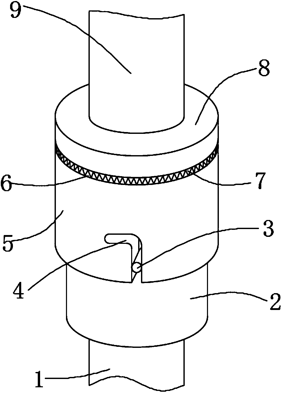
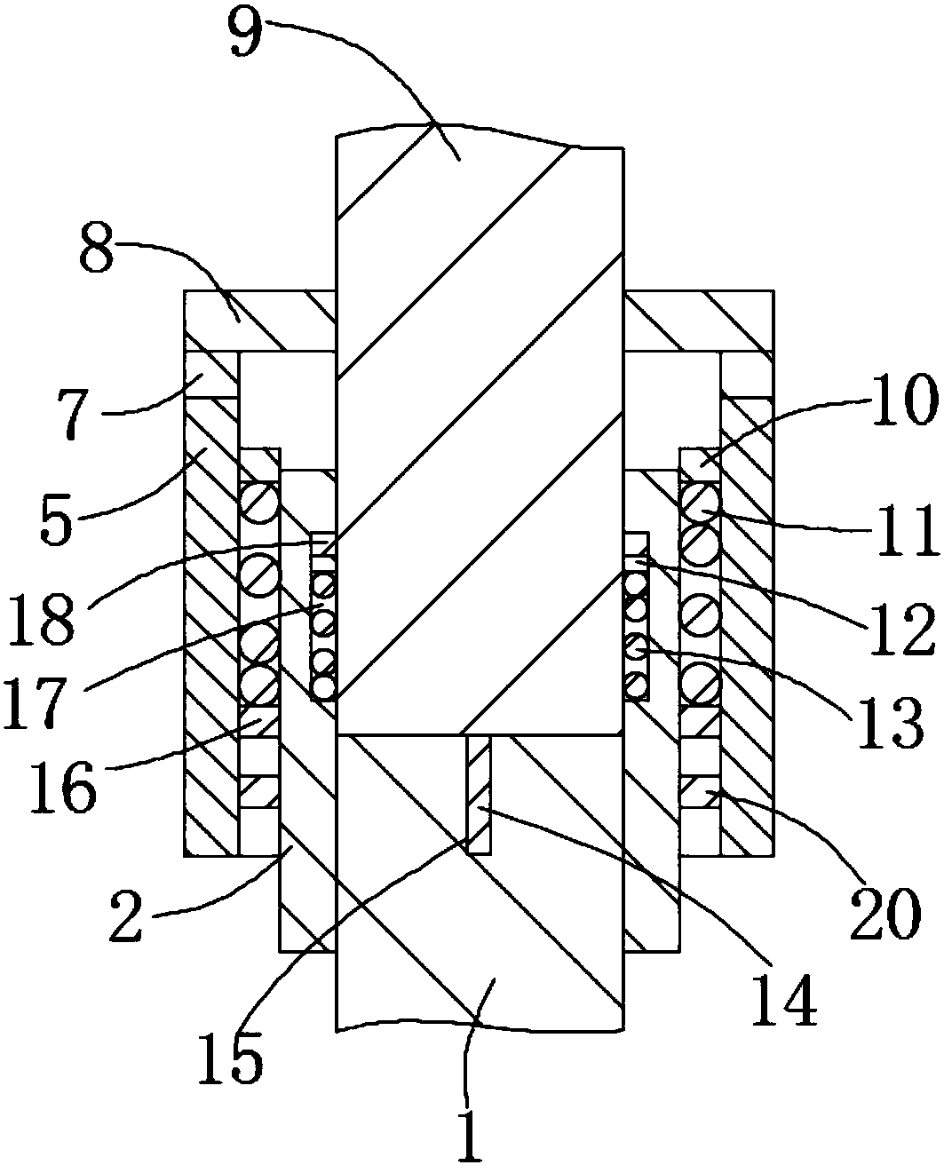
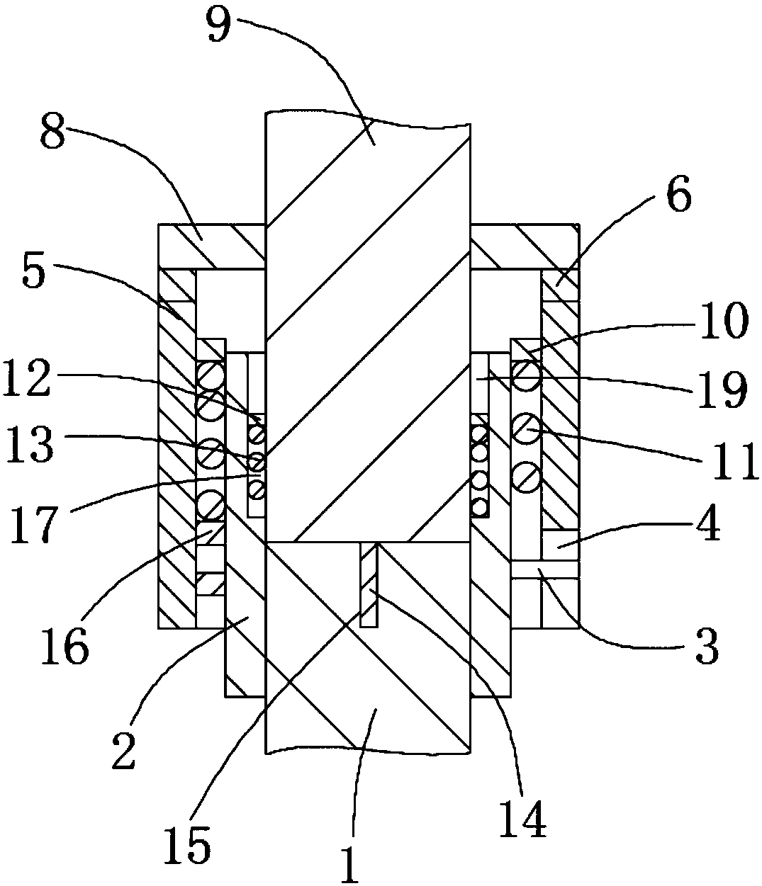
[0017] see Figure 1-3 , the present invention provides a technical solution: a split-type coaxial radio frequency connector, including a first joint 1 and a second joint 9, one end of the first joint 1 is fixedly sleeved in one end of the connecting pipe 2, and the second joint One end of 9 is slidably socketed in the other end of connecting pipe 2, a pinhole 15 is opened at one end of the first joint 1, and a pin 14 is fixedly installed at one end of the sec...


PUM


Abstract

The invention discloses a split type coaxial radio-frequency connector. The connector comprises a first joint and a second joint, wherein the first joint is fixedly nested at one end of a connecting pipe, the second joint is glidingly nested at the other end of the connecting pipe, a radial sliding chute and an axial sliding chute are formed in the inner wall of the connecting pipe, a second spring is mounted in the radial sliding chute and connected with a press ring, the press ring is pressed under a second slider, the second slider is mounted on the second joint, the connecting pipe is sleeved with a sliding sleeve, a first toothed block is mounted at the top of the sliding sleeve, the second joint is sleeved with a cover plate, a second toothed block is mounted at the bottom of the cover plate, and the first toothed block is meshed with the second toothed block. The second joint is inserted into the connecting pipe, the second joint is rotated, the second slider slides into the radial sliding chute, the press ring presses the second slider, the sliding sleeve moves upwards, so that the first toothed block and the second toothed block are meshed, the cover plate is locked by thesliding sleeve and cannot rotate, the second joint cannot rotate, and the condition that the second joint is separated out of the connecting pipe during shaking of the connector is avoided.

Description

technical field [0001] The invention relates to the technical field of communication electronic equipment, in particular to a split-type coaxial radio frequency connector. Background technique [0002] Coaxial RF connectors are referred to as RF connectors for short. They are usually a component that is attached to a cable or installed on an instrument. As a component that is electrically connected or separated from a transmission line, common coaxial RF connectors are threaded. A stud is set outside one terminal of the connector, and a nut is installed outside the other terminal, and the nut and the stud are connected together so that the two terminals are connected. However, repeated rotation of the nut during threaded connection is likely to cause pin insertion at the connection end. Bending, and installation and disassembly steps are cumbersome. If the connector shakes, the thread is easy to loosen, resulting in unstable signal transmission. Therefore, we propose a split...

Claims


Application Information

Patent Timeline
Patent Type & Authority Applications(China)
IPC IPC(8): H01R13/52H01R13/625H01R13/639H01R24/00H01R24/40
CPCH01R13/639H01R13/5219H01R13/625H01R24/00H01R24/40
Inventor 徐军荣徐志业
Owner ZHENJIANG YONGWO COPPER IND CO LTD
Why Eureka
Try Eureka