Control device and control method of led lamp source

A technology of an LED lamp and a control method is applied in the field of control devices to achieve the effect of avoiding frequent connection

Inactive Publication Date: 2018-08-31
高远
View PDF7 Cites 0 Cited by
  • Summary
  • Abstract
  • Description
  • Claims
  • Application Information

AI Technical Summary

Problems solved by technology

[0004] It is an object of the present application to overcome the above-mentioned problems or to at least partially solve or alleviate the above-mentioned problems

Method used


Image

  • Control device and control method of led lamp source
  • Control device and control method of led lamp source
  • Control device and control method of led lamp source

Examples


Embodiment Construction

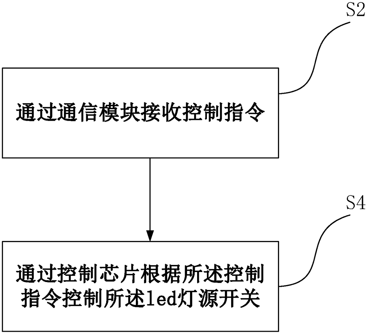
[0024] Please refer to figure 1 , In an embodiment of the present application, the LED light source control device includes: a control chip; a communication module connected to the control chip for receiving control instructions. The control command sent by the smart terminal is received through the communication module, and the control chip transmits the control command to the controlled LED light source. Therefore, the purpose of controlling the LED light source can be controlled according to the control instructions of the smart terminal.

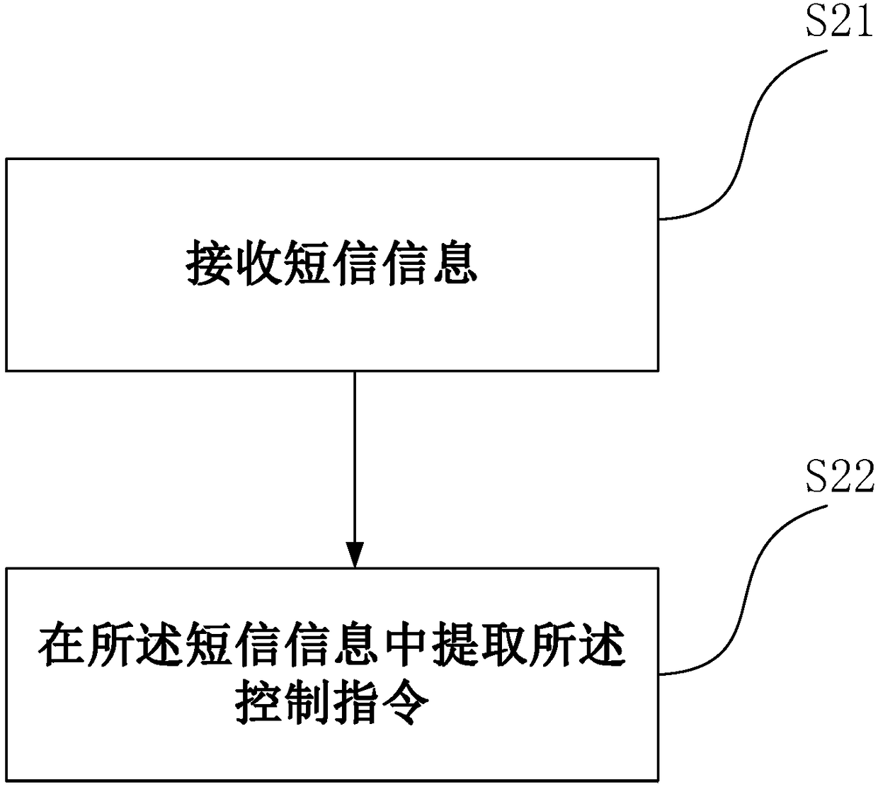
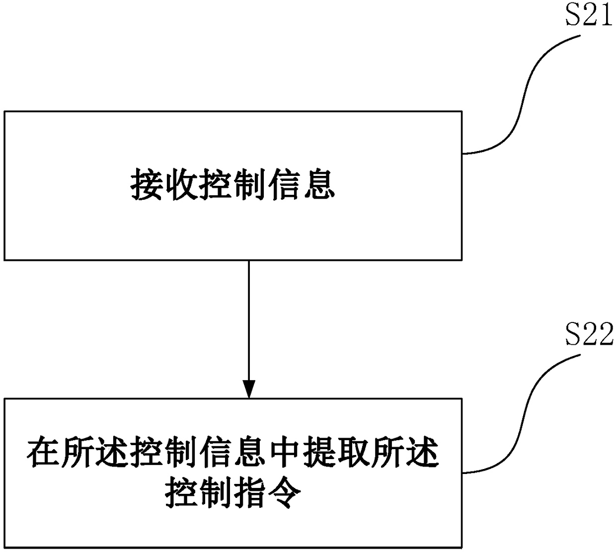
[0025] In an embodiment of the present application, the smart terminal is a mobile phone, and the control command is a mobile phone text message. But it is not limited thereto, and those skilled in the art can determine the type of the smart terminal and the type of the control instruction according to the actual situation. When in use, the controller writes the control instructions in the text message, such as wanting the LED light to...


PUM


Abstract

The invention discloses a control device and control method of a led lamp source. The control device comprises a control chip and a communication module, wherein the communication module is connectedwith the control chip, is used for receiving a control instruction and is a message communication module. With the control device of the led lamp source, provided by the invention, remote control canbe achieved by a message channel, and meanwhile, normal connection of GPRS is prevented.

Description

technical field [0001] The present application relates to a control device, in particular to a light source control device. Background technique [0002] The current outdoor LED lighting control is mainly divided into two categories, one is to insert the SD card, write the transformation mode of the outdoor LED lighting in the SD card, and then realize the lighting control, and the other is through the TCP / IP protocol to realize real-time control in LAN. [0003] For the first method, manual on-site control is required, which wastes labor costs. For the second method, a constant connection of GPRS is required, which will put a lot of pressure on the server, from the perspective of use cost and maintenance cost. Contents of the invention [0004] It is an object of the present application to overcome the above-mentioned problems or to at least partially solve or alleviate the above-mentioned problems. [0005] According to one aspect of the present application, a method...

Claims


Application Information

Patent Timeline
Patent Type & Authority Applications(China)
IPC IPC(8): H05B33/08H04W4/14G08C17/02H05B44/00
CPCH04W4/14G08C17/02H05B45/00Y02B20/30
Inventor 高远
Owner 高远
Why Eureka
Try Eureka