Glass external wall cleaning robot based on vacuum suction cup control

A technology for cleaning robots and glass exterior walls. It is used in robot cleaning machines, cleaning machinery, and window cleaning. It can solve problems such as hidden safety hazards, damage to cleaning robots and obstacles, and large shaking of cleaning robots.

Inactive Publication Date: 2018-09-04
欧阳慧琳
View PDF0 Cites 1 Cited by
  • Summary
  • Abstract
  • Description
  • Claims
  • Application Information

AI Technical Summary

Problems solved by technology

[0002] At present, the existing glass cleaning robot has a simple structure. Generally, wire rope fishing is used to clean the glass on the outer wall of a high-rise building. This fixing method has great potential safety hazards, because the cleaning robot is fixed and guided at the height of the high-rise building. Under the action of gravity, the cleaning robot will sway back and forth. At the same time, when the cleaning robot is switching between different working surfaces, the traditional cleaning robot relies on wire ropes to switch, which will make the cleaning robot slosh even more. Such a swaying cleaning robot will encounter obstacles in the air, which will cause damage to both the cleaning robot and the obstacles, thus causing unnecessary losses. In order to avoid this kind of phenomenon, a glass based on vacuum suction cup control is designed Exterior wall cleaning robot is very necessary

Method used


Image

  • Glass external wall cleaning robot based on vacuum suction cup control
  • Glass external wall cleaning robot based on vacuum suction cup control
  • Glass external wall cleaning robot based on vacuum suction cup control

Examples


Embodiment Construction

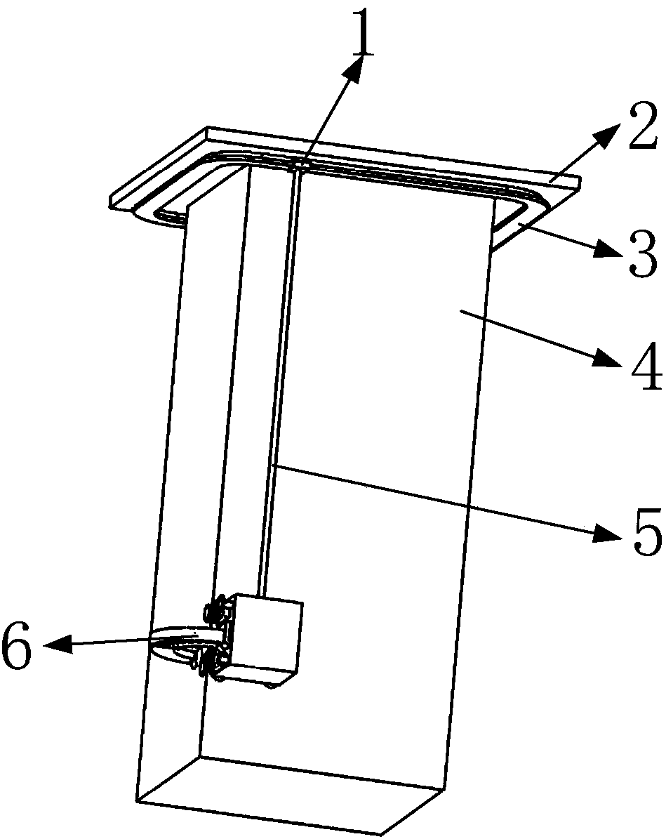
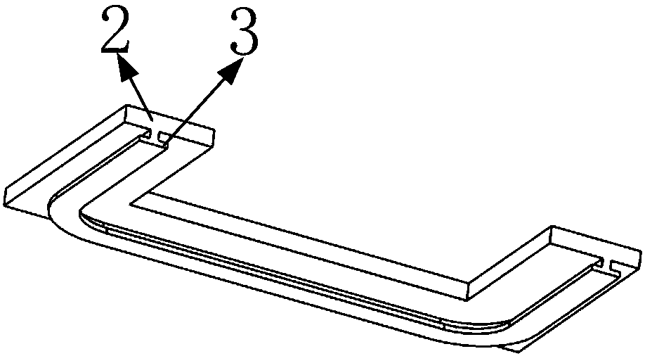
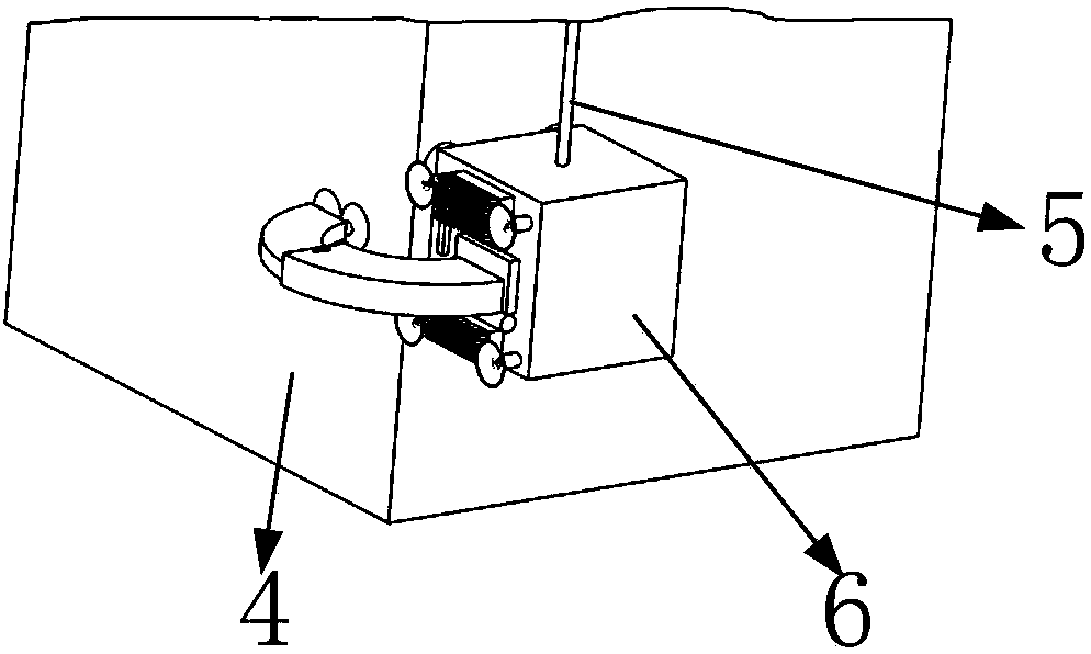
[0040] Such as figure 1 As shown, the back-shaped fixed plate 2 is installed on the upper side of the tall building 4; as figure 2 As shown, the back-shaped T-shaped bar 3 is installed on the lower end face of the back-shaped fixed plate 2; as Figure 5 As shown, the end face of the first T-shaped block 1 is provided with a through first T-shaped slot 8; as figure 1 As shown, the first T-shaped block 1 is installed in cooperation with the back-shaped T-shaped bar 3 through the first T-shaped groove 8; as Figure 4 As shown, one end of the steel wire rope 5 is installed on the end face of the first T-shaped block 1; as image 3 As shown, the cleaning robot mechanism 6 is installed on the steel wire rope 5, and the cleaning robot mechanism 6 cooperates with the tall building 4.

[0041] Such as Image 6 As shown, the above-mentioned cleaning robot mechanism 6 includes a first pipeline 9, a first suction cup 10, a track mechanism 11, a first circular hole 12, a second suctio...


PUM


Abstract

The invention belongs to the technical field of glass cleaning robots, and particularly relates to a glass external wall cleaning robot based on vacuum suction cup control. The glass external wall cleaning robot comprises a first pipeline, a first suction cup, a track mechanism, a first round hole, a second suction cup, a third suction cup, a second pipeline, a fourth suction cup, a third pipeline, a fixing shell, second round holes, a first square hole, a first semicircular groove, a second square hole, a third square hole and the like, the end face of the fixing shell is provided with the first square hole; the end face, provided with the first square hole, of the fixing shell is provided with the first semicircular groove which is located on the lower side of the first square hole; andthe two sets of second round holes are symmetrically formed in the upper side and the lower side of the end face, provided with the first square hole, of the fixing shell. A sensing device is mountedon the end face, provided with the second square hole, of the fixing shell and used for sensing whether a cleaning robot mechanism turns or crosses barriers. When glass on a tall building external wall is cleaned through the glass external wall cleaning robot, the effects of automatically switching cleaned wall faces and crossing the barriers on the same cleaned wall face are achieved.

Description

technical field [0001] The invention belongs to the technical field of glass cleaning robots, in particular to a glass exterior wall cleaning robot based on vacuum suction cup control. Background technique [0002] At present, the existing glass cleaning robot has a simple structure. Generally, wire rope fishing is used to clean the glass on the outer wall of a high-rise building. This fixing method has great potential safety hazards, because the cleaning robot is fixed and guided at the height of the high-rise building. Under the action of gravity, the cleaning robot will sway back and forth. At the same time, when the cleaning robot is switching between different working surfaces, the traditional cleaning robot relies on wire ropes to switch, which will make the cleaning robot slosh even more. Such a swaying cleaning robot will encounter obstacles in the air, which will cause damage to both the cleaning robot and the obstacles, thus causing unnecessary losses. In order to ...

Claims


Application Information

Patent Timeline
Patent Type & Authority Applications(China)
IPC IPC(8): A47L1/02A47L11/38A47L11/40
CPCA47L1/02A47L11/38A47L11/40A47L11/4061A47L11/4066A47L2201/00A47L2201/04B25J11/0085B62D57/024
Inventor 不公告发明人
Owner 欧阳慧琳
Why Eureka
Try Eureka