
Improved shower head button switching structure

A button and shower technology, applied in the bathroom field, can solve the problems of unsmooth switching, easy deformation of levers, large height space, etc., to avoid unsmooth switching, simple and ingenious operation, and improve stability.

Pending Publication Date: 2018-09-04
PURITY XIAMEN SANITARY WARE
View PDF7 Cites 7 Cited by
  • Summary
  • Abstract
  • Description
  • Claims
  • Application Information

AI Technical Summary

Problems solved by technology

[0004] Its disadvantages are: 1. The connection between the pull rod and the driving disc needs to be fixedly connected. During the action, the pull rod is easily deformed or even stuck, resulting in unsmooth switching; 2. The driving disc and the driven disc need to be set up and down, and the larger height space, so it is necessary to design the shower body with a larger thickness, so that the entire product
Specifically, this structure uses the ratchet teeth on the inner ring of the ratchet wheel to cooperate with the elastic claws on the ratchet to achieve the purpose of synchronous rotation of the ratchet and the ratchet. Cooperate with the next ratchet to achieve the purpose of non-return. The defects of the switching outlet structure are: 1) The movement of the entire product is driven by the pull rod, which is not easy to control; 2) The elastic claw is deformed, which may easily cause the ratchet to get stuck when it is reset. , resulting in reset failure and affecting the next switching process. 3) The push rod is connected to the ratchet through the groove and the protrusion embedded in the groove. This connection method is not stable enough

Method used


Image

  • Improved shower head button switching structure
  • Improved shower head button switching structure
  • Improved shower head button switching structure

Examples


Embodiment Construction

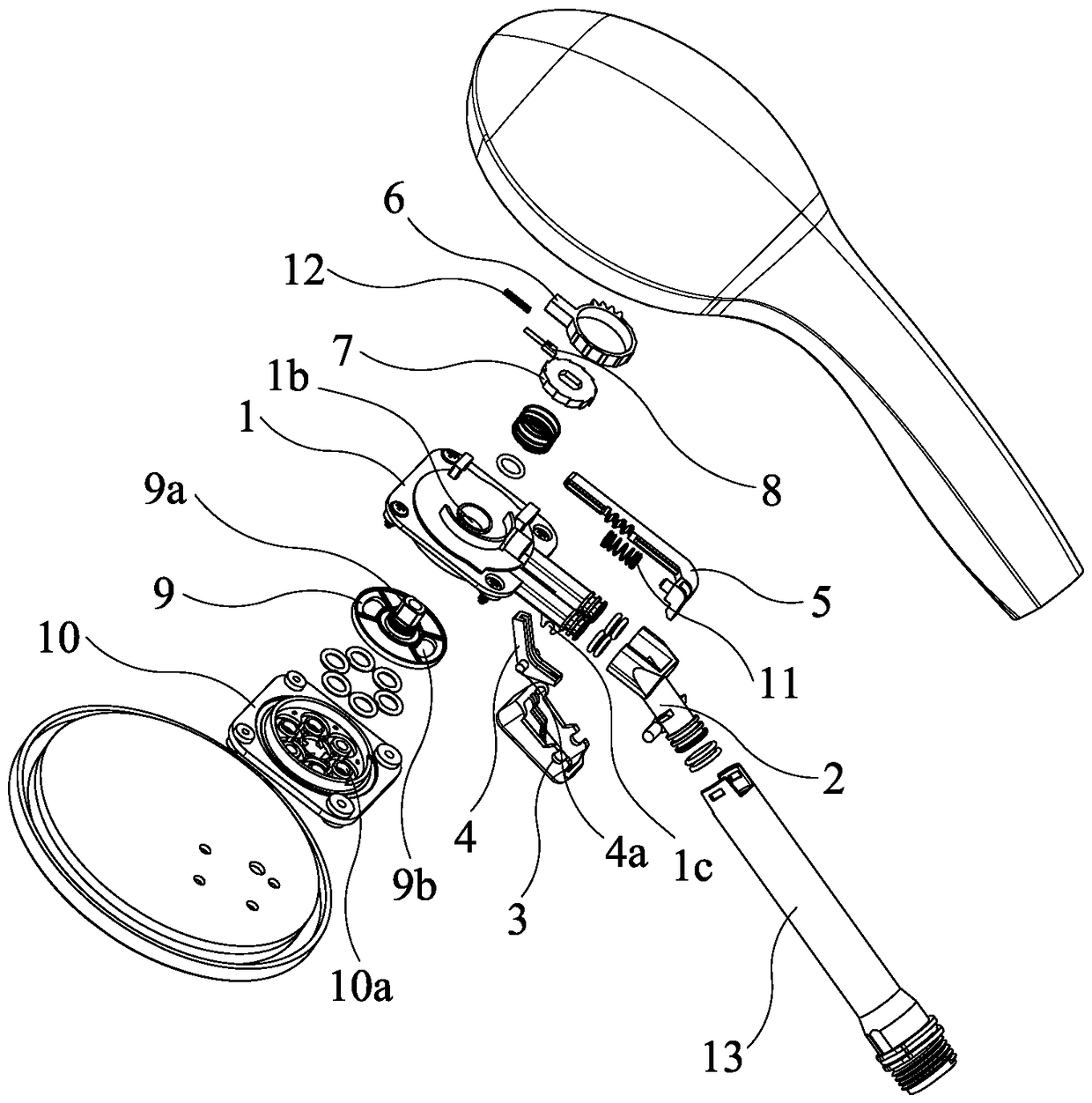
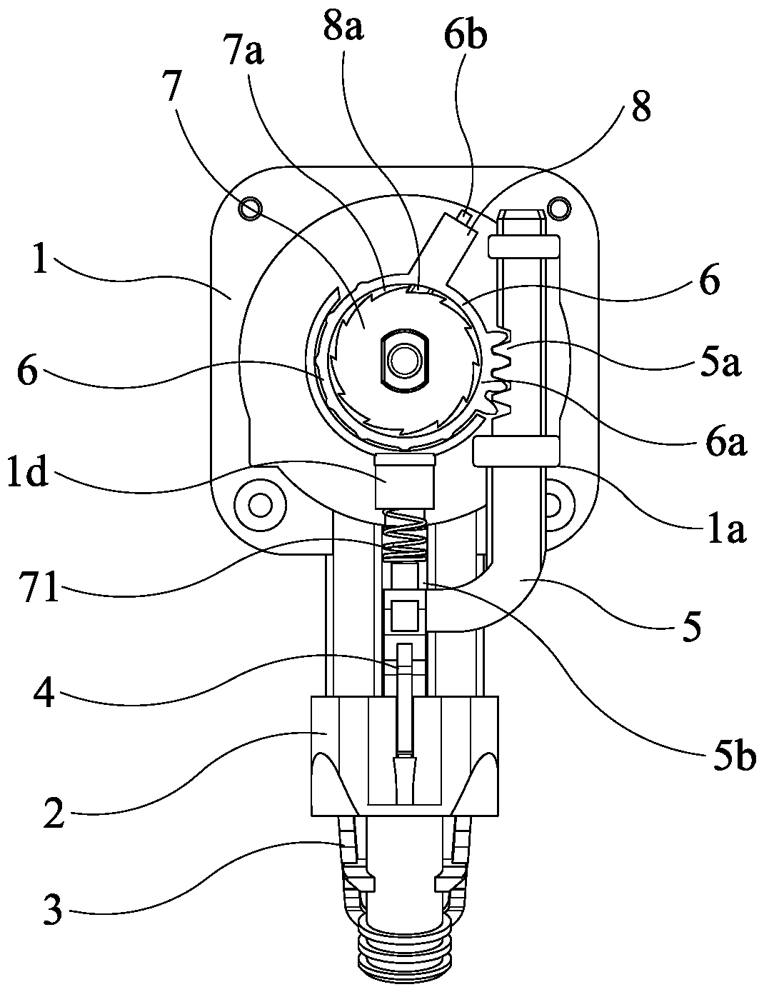
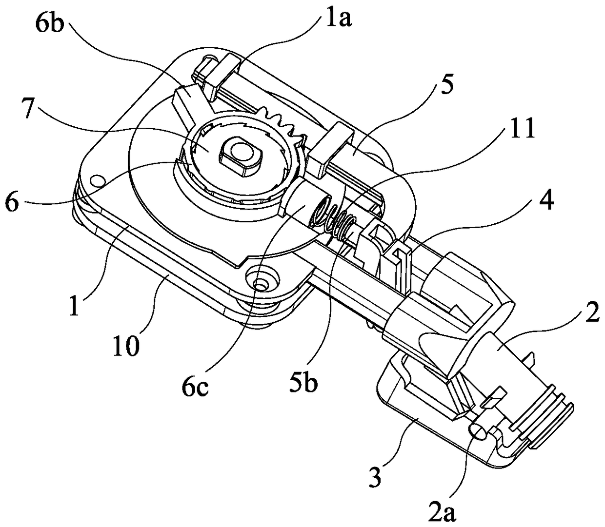
[0043] like Figure 1-5 As shown, the present invention discloses an improved shower button switching structure, including a water sealing seat 1, a fixed seat 2, a button 3, a push block 4, a push rod 5, a driving disc 6, a driven disc 7, a positioning block 8, a sealing Water tray 9 and water sealing surface cover 10;

[0044] The middle end of the push block 4 is pivotally arranged on the water sealing seat 1, and the free end of the button 3 is connected to one end of the push block 4 in such a way that it can be pushed down to push the push block 4 up; the upper surface of the water sealing seat 1 forms a limiting guide groove 1a , the push rod 5 is L-shaped, the front end of the push rod 5 is inserted into the limit guide groove 1a, and the push rod 5 can move back and forth under the guidance of the limit guide groove, and the rear end of the push rod 5 is linked with the other end of the push block 4 , when the push block 4 swings up, it can drive the push rod 5 to mo...


PUM


Abstract

The invention discloses an improved shower head button switching structure. The improved shower head button switching structure comprises a water sealing base, a fixed base, a button, a pushing block,a push rod, a driving disc, a driven disc, a locating block and a water sealing disc, wherein a gear part is formed on the periphery of the driving disc, a rack is formed at the front end of the pushrod, and the push rod can drive the driving disc to move in the back-and-forth reciprocating moving process; and the driven disc is nested in the driving disc, the locating block is installed in thedriving disc in an inclined manner, and a circle of ratchet teeth are formed in the periphery of the driven disc. According to the improved shower head button switching structure, a smoother and morestable water flow switching function can be achieved.

Description

technical field [0001] The invention relates to the technical field of sanitary ware, in particular to an improved switchover structure of a shower button. Background technique [0002] The button switching structure in the bathroom industry is to push a pull rod connected with the driving plate through the button, so as to drive the upper or lower driven plate, and then drive the rotation of the water sealing plate, so as to realize the switching of the splash function. [0003] CN201420658855 discloses a button-controlled water outlet terminal mechanism, which adopts a linkage mechanism composed of a push block and a pull rod. Its feature is that the button drives the driven switching component through the linkage mechanism to realize water flow switching. The specific action is: press Push the button, push the push block, the push rod will pull the pull rod backward, and the pull rod will be linked (rotated) with the driving disc. The rotation of the driving plate drives...

Claims


Application Information

Patent Timeline
Patent Type & Authority Applications(China)
IPC IPC(8): B05B1/16B05B1/18B05B12/00
CPCB05B1/1636B05B1/18B05B12/002
Inventor 杨习文黄加源凌兴传吴国忠吴伟圣吴金龙
Owner PURITY XIAMEN SANITARY WARE
Learn More