Device for grinding agricultural mechanical steel rings

A technology for agricultural machinery and steel rings, which is applied in the direction of grinding drive devices, grinding machine parts, grinding machines, etc., and can solve the problems of impossibility of consistent grinding marks, high labor intensity, and incomplete grinding of burrs.

Inactive Publication Date: 2018-09-04
常州特速安机电科技有限公司
View PDF0 Cites 0 Cited by
  • Summary
  • Abstract
  • Description
  • Claims
  • Application Information

AI Technical Summary

Problems solved by technology

[0003] The invention proposes a grinding device for the steel ring of agricultural machinery, which solves the problem that in the prior art, the grinding method of the steel ring of agricultural machinery is that the grinding marks cannot be consistent, the burr grinding is not necessarily thorough, and the grinding quality cannot be guaranteed. , followed by the problem of high labor intensity and harsh working conditions. The present invention passes the central hole of the steel ring through the provided rotating shaft and places it on one side of the baffle. The connecting rod passes through the inner hole of the steel ring, and the pressing rod is rotated to make The pressing block is pressed on the inner side of the steel ring, and then the nut is tightened to fix the steel ring, and the second cylinder drives the grinding head up and down, so that the grinding head falls to the position where it contacts the steel ring, and the motor works so that the rotating shaft drives the steel ring to rotate for grinding , and the first cylinder can drive the push block to move, and then adjust the horizontal position of the grinding head

Method used


Image

  • Device for grinding agricultural mechanical steel rings
  • Device for grinding agricultural mechanical steel rings

Examples


Embodiment 1

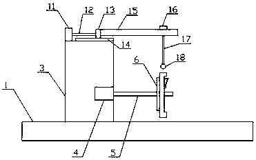
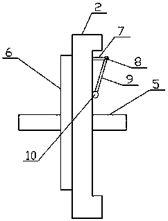
[0018] like Figure 1-2 As shown, the present invention provides a grinding device for steel rings of agricultural machinery, including a base plate 1 and a steel ring 2, a chassis 3 is provided on the top side of the bottom plate 1, a motor 4 is provided in the chassis 3, and the motor 4 One side is connected to the rotating shaft 5, the rotating shaft 5 is provided with a baffle plate 6, one side of the baffle plate 6 is in contact with the steel ring 2, and one side of the baffle plate 6 is provided with a connecting rod 7, and the connecting rod 7 One side is connected with a compression rod 9 through a screw 8, the bottom of the compression rod 9 is connected with a compression block 10, and the top of the chassis 3 is provided with a first cylinder 11, and one side of the first cylinder 11 is connected with the first drive Rod 12, one side of the first driving rod 12 is connected with a push block 13, one side of the first cylinder 11 is provided with a chute 14, the pus...


PUM


Abstract

The invention relates to a device for grinding agricultural mechanical steel rings. The device comprises a bottom plate and a steel ring, wherein a motor box is arranged at one side of the top of thebottom plate; a motor is arranged in the motor box; a rotating shaft is connected at one side of the motor; a baffle plate is arranged on the rotating shaft; the steel ring is in contact connection with one side of the baffle plate; a connecting rod is arranged at one side of the baffle plate; a pressing rod is connected at one side of the connecting rod through a screw; a pressing block is connected at the bottom of the pressing rod; and a first cylinder is arranged on the top of the motor box. When the device is in use, the arranged rotating shaft passes through the central hole of the steelring and the steel ring is placed at one side of the baffle plate; the connecting rod passes through an inner hole of the steel ring; the pressing rod is rotated to press the pressing block on the inner side of the steel ring; a nut is tightened to fix the steel ring; a polishing head is driven to go up and down through a second cylinder to ensure that the grinding head goes down to the positionin contact with the steel ring; the motor works to drive the rotating shaft to rotate the steel ring for grinding; and a pushing block can be driven by the first cylinder to move so as to adjust the horizontal position of the grinding head.

Description

technical field [0001] The invention relates to a grinding device for steel rings of agricultural machinery, which belongs to the field of agricultural machinery. Background technique [0002] In the production of automobile wheel steel rings, there is a grinding process for the burrs on both sides of the steel rings. The traditional method is pure manual grinding. During manual grinding, a table with two rotatable rollers is set up, and the steel rings to be polished are placed On the drum, one hand controls the regular rotation of the steel ring, and the other hand uses a hand grinder to grind the burrs on both sides of the steel ring. This primitive grinding method is first of all that the grinding marks cannot be consistent, and the burrs are not necessarily polished. Thoroughly, the quality of grinding cannot be guaranteed, followed by high labor intensity and harsh working conditions. Contents of the invention [0003] The invention proposes a grinding device for th...

Claims


Application Information

Patent Timeline
Patent Type & Authority Applications(China)
IPC IPC(8): B24B5/35B24B5/36B24B41/06B24B47/12B24B47/20
CPCB24B5/363B24B5/35B24B41/067B24B47/12B24B47/20
Inventor 付凤吉
Owner 常州特速安机电科技有限公司
Why Eureka
Try Eureka