Universal board card test fixture

A test fixture, a general-purpose technology, applied in the direction of measuring devices, measuring electrical variables, measuring device casings, etc., can solve problems such as component damage, uneven force on the main board, and complicated operations

Active Publication Date: 2021-02-02
SUZHOU LANGCHAO INTELLIGENT TECH CO LTD
View PDF1 Cites 0 Cited by
  • Summary
  • Abstract
  • Description
  • Claims
  • Application Information

AI Technical Summary

Problems solved by technology

The main board is not a smooth plane. Various components and card slots are welded on the front and back, such as chips, memory card slots, etc. In addition, heat sinks, memory and other boards are inserted during testing and placed directly on the workbench , the first aspect, the uneven force on the motherboard, the second aspect, there is a risk of damage to components, etc., the third aspect, it is not easy to assemble and test, etc.
[0003] Different types of motherboards are different in size and appearance. The general shape of the motherboard is not fixed. Some are L-shaped, some are U-shaped, and some are rectangular, especially the mounting holes of the motherboard. The location is different, and the clamping and supporting methods must be universal; the existing technology is assembled by a metal frame to support the main board, but the existing equipment is targeted, that is, one equipment corresponds to one type of main board, which cannot be used universally; the structure is complex , poor applicability
The cost of a single device is high, and it needs to be clamped and fixed by tools
The patent (application number: 201710742998.6) discloses a universal motherboard test bench, but the operation is complicated. Now in order to reduce costs and increase versatility, a simple fixture that is easy to operate and modular is needed

Method used


Image

  • Universal board card test fixture
  • Universal board card test fixture
  • Universal board card test fixture

Examples


Embodiment Construction

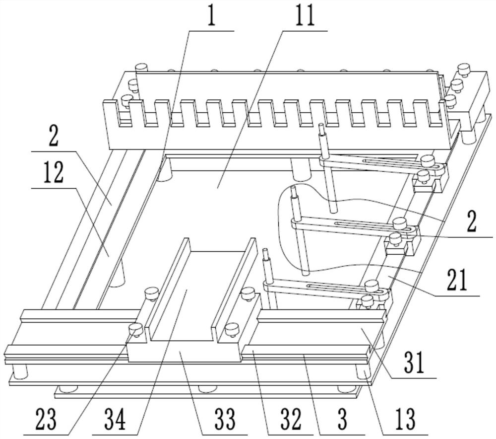
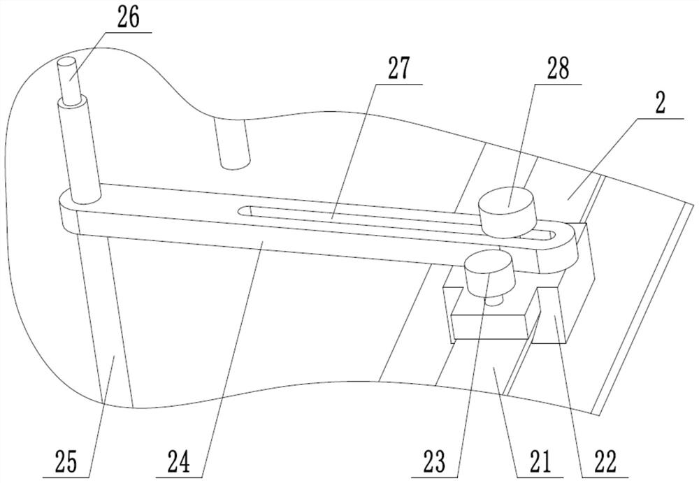
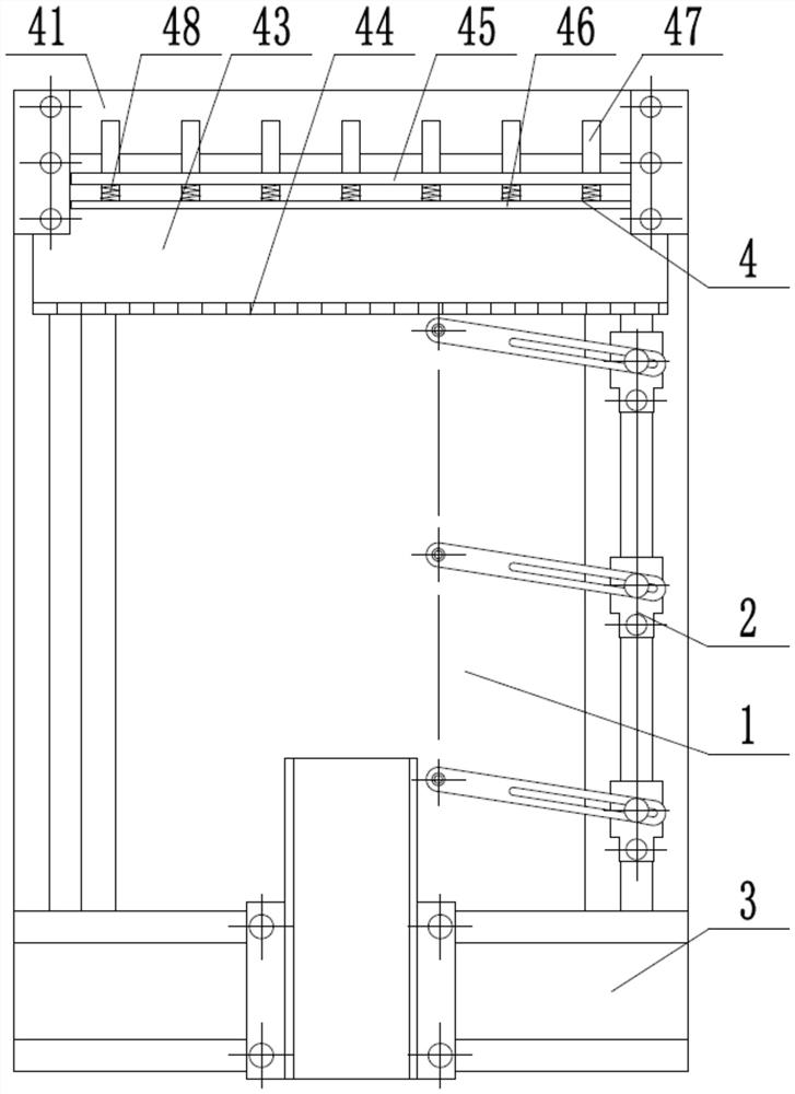
[0030] In order to clearly illustrate the technical features of the present solution, the present invention will be described in detail below through specific implementation methods and in conjunction with the accompanying drawings. The following disclosure provides many different embodiments or examples for implementing different structures of the present invention. To simplify the disclosure of the present invention, components and arrangements of specific examples are described below. Furthermore, the present invention may repeat reference numerals and / or letters in different instances. This repetition is for the purpose of simplicity and clarity and does not in itself indicate a relationship between the various embodiments and / or arrangements discussed. It should be noted that components illustrated in the figures are not necessarily drawn to scale. Descriptions of well-known components and processing techniques and processes are omitted herein to avoid unnecessarily lim...


PUM


Abstract

The invention discloses a universal board card test fixture which comprises a bracket, a mainboard mounting frame, a power supply frame and a fan frame, and is characterized in that the mainboard mounting frame, the power supply frame and the fan frame are all mounted on the bracket; the mainboard mounting frame comprises a mounting frame guide rail and a sliding positioning piece; the mounting frame guide rail is mounted on the bracket, the sliding positioning piece is matched with the mounting rack guide rail and mounted on the bracket, and the sliding positioning piece is matched with a to-be-tested board card; the power supply frame supports the power supply of the to-be-tested board card in a matched mode, the power supply frame is installed on the bracket, and the fan frame supportsthe cooling fan of the to-be-tested board card in a matched mode and is installed on the bracket. The to-be-tested board card is generally unfixed in shape, L-shaped, U-shaped and rectangular, the position of the sliding positioning piece is adjusted, the sliding positioning piece is matched with the mounting hole of the to-be-tested board card, the power supply frame drags the power supply matched with the to-be-tested board card, the position of the power supply frame can also be adjusted, and it is guaranteed that the fixture can adapt to various to-be-tested board cards.

Description

technical field [0001] The invention relates to the technical field of server mainboard testing, in particular to a universal board testing fixture. Background technique [0002] In the process of product development and testing, various types of main boards are often tested. Currently, the main board is tested by directly placing the main board on an anti-static workbench. The main board is not a smooth plane. Various components and card slots are welded on the front and back, such as chips, memory card slots, etc. In addition, heat sinks, memory and other boards are inserted during testing and placed directly on the workbench , Firstly, the force on the motherboard is not uniform, secondly, there is a risk of damage to components, etc., thirdly, it is not easy to assemble and test. [0003] Various types of motherboards are different in size and appearance. The general shape of the motherboard is not fixed. Some are L-shaped, some are U-shaped, and some are rectangular. E...

Claims


Application Information

Patent Timeline
Patent Type & Authority Applications(China)
IPC IPC(8): G01R1/04
CPCG01R1/04G01R1/0408
Inventor 鲁璐张运广胡蒙
Owner SUZHOU LANGCHAO INTELLIGENT TECH CO LTD
Why Eureka
Try Eureka