Quick magnet pressing machine
A press-fitting machine and fast technology, applied in the directions of hand-held tools, manufacturing tools, etc., can solve the problems of low assembly efficiency, high labor intensity, complicated steps, etc., and achieve the effects of convenient operation, reduced labor intensity, and improved assembly efficiency.
- Summary
- Abstract
- Description
- Claims
- Application Information
AI Technical Summary
Problems solved by technology
Method used
Image
Examples
Embodiment 1
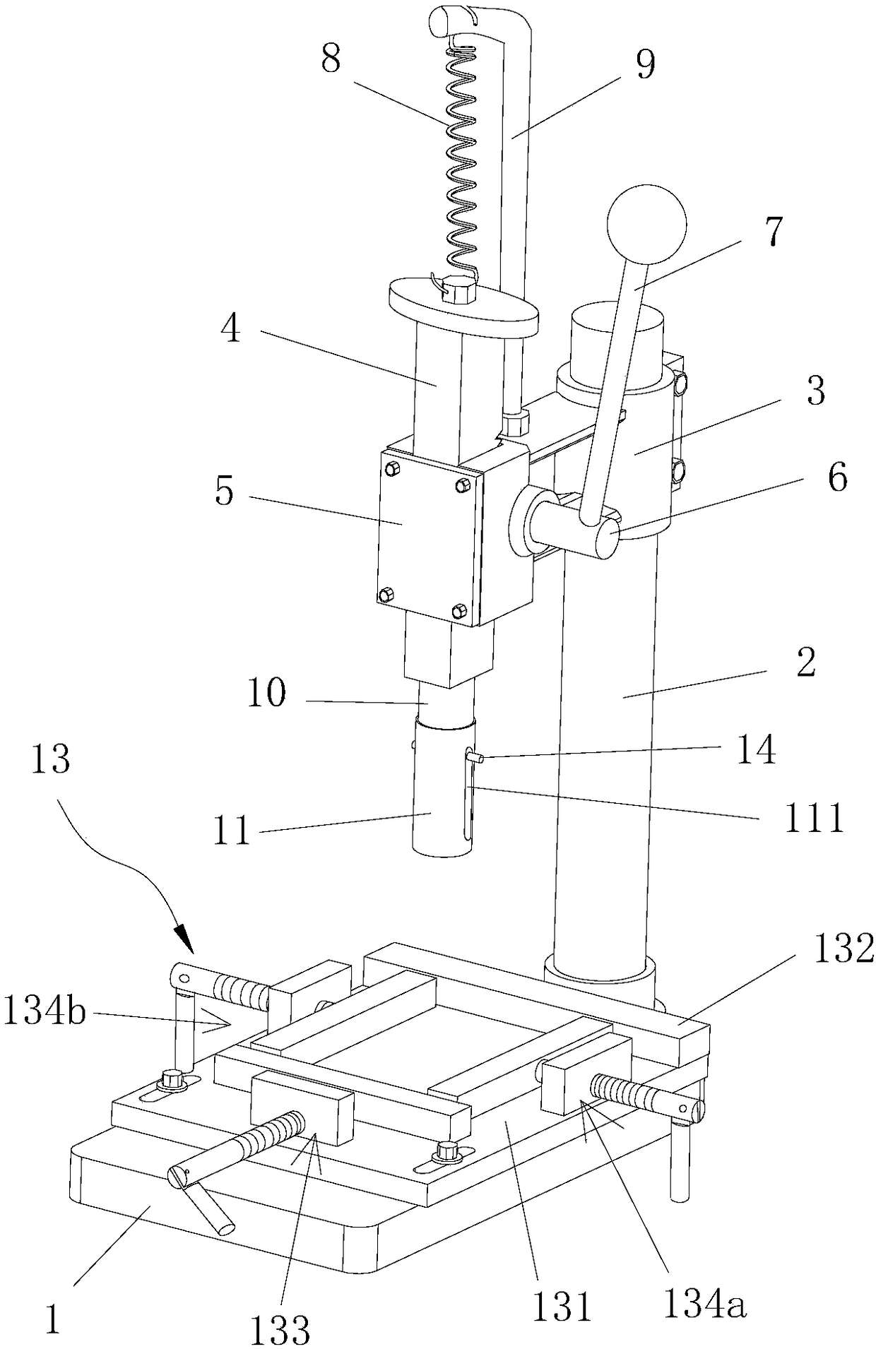
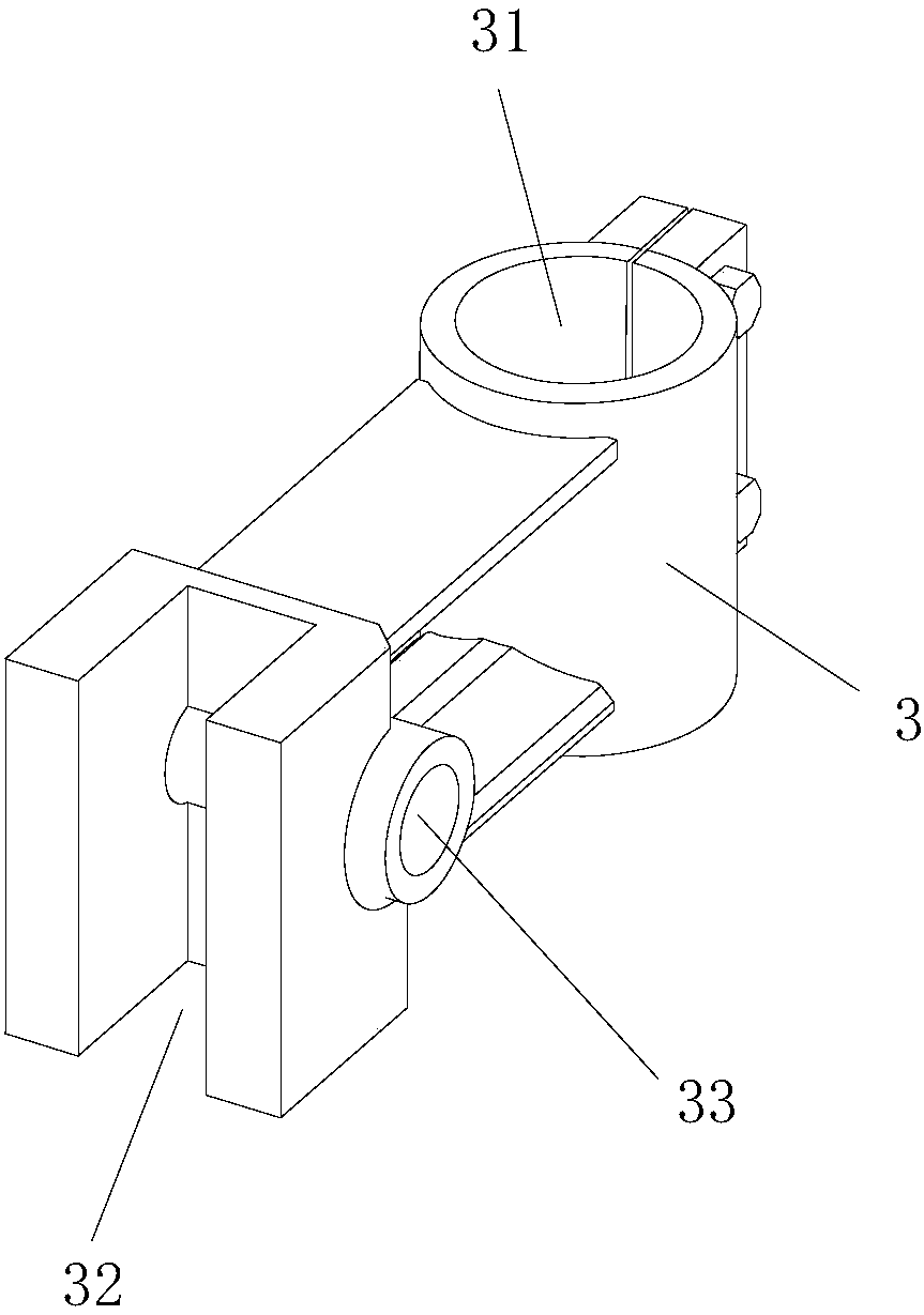
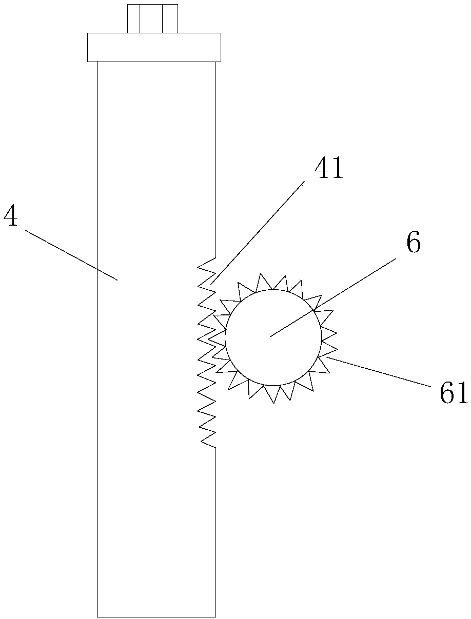
[0029] Please refer to figure 1 , Embodiment 1 of the present invention provides a quick magnet press-fitting machine, including a base 1, a support column 2, a body base 3, a rack 4, a cover plate 5, a rotating shaft 6, an operating handle 7, a spring 8, a spring installation Rod 9, pressing rod 10, positioning conduit 11 for storing and guiding and positioning the magnetic strips that are stacked and attracted together by a plurality of magnets 20 to be pressed, for distinguishing the polarity of the two ends of the magnetic strips and One end of the magnetic strip with the opposite polarity is attracted to fix the magnetic strip inside the positioning guide 11 and the positioning fixture device 13 for positioning the workpiece 30 to be assembled. The following describes the various components of this embodiment in conjunction with the accompanying drawings. Detailed description.
[0030] Such as figure 2 As shown, the rear end of the fuselage base 3 is provided with a lo...
Embodiment 2
[0041] Embodiment 2 of the present invention provides another quick magnet press-fitting machine, which also includes a base 1, a support column 2, a body seat 3, a rack 4, a cover plate 5, a rotating shaft 6, an operating handle 7, a spring 8, Spring mounting rod 9, pressing rod 10, positioning guide 11 for accommodating and guiding and positioning the magnetic strips that are stacked and attracted together by a plurality of magnets 20 to be pressed, and for distinguishing the poles at both ends of the magnetic strips The magnet 12 and the positioning fixture device 13 used to position the workpiece 30 to be assembled, the structure of the second embodiment is the same as that of the above-mentioned embodiment. Most of the structures of Example 1 are the same, and the similarities will not be repeated. The difference is that: Figure 10 As shown, the limiting structure between the pressing rod 10 and the positioning guide 11 includes a first stop 112 arranged on the inner wal...
Embodiment 3
[0043] Embodiment 3 of the present invention provides another quick magnet press-fitting machine, which also includes a base 1, a support column 2, a body base 3, a rack 4, a cover plate 5, a rotating shaft 6, an operating handle 7, a spring 8, Spring mounting rod 9, pressing rod 10, positioning guide 11 for accommodating and guiding and positioning the magnetic strips that are stacked and attracted together by a plurality of magnets 20 to be pressed, and for distinguishing the poles at both ends of the magnetic strips and the opposite polarity of the magnetic strip end is attracted together to fix the magnetic strip inside the positioning guide 11. The magnet 12 and the positioning fixture device 13 for positioning the workpiece 30 to be assembled, the structure of the third embodiment is the same as the above-mentioned implementation The structures of example one or embodiment two are mostly the same, and the similarities will not be repeated, and the difference is: as Figu...
PUM
 Abstract
Description
Claims
Application Information
 - R&D
- Intellectual Property
- Life Sciences
- Materials
- Tech Scout
- Unparalleled Data Quality
- Higher Quality Content
- 60% Fewer Hallucinations
Browse by: Latest US Patents, China's latest patents, Technical Efficacy Thesaurus, Application Domain, Technology Topic, Popular Technical Reports.
© 2025 PatSnap. All rights reserved.Legal|Privacy policy|Modern Slavery Act Transparency Statement|Sitemap|About US| Contact US: help@patsnap.com


