
Gravity Field Density Inversion Method Based on Quasi Radial Basis Function Neural Network

A neural network and density inversion technology, applied in the field of geophysical inversion, can solve the problems of inability to improve the vertical resolution of gravity inversion and ill-posed gravity inversion, so as to improve the vertical resolution and reliability, Explanatory clear and unambiguous effect

Active Publication Date: 2019-11-08
CHINA PETROLEUM & CHEM CORP +1
View PDF1 Cites 0 Cited by
  • Summary
  • Abstract
  • Description
  • Claims
  • Application Information

AI Technical Summary

Problems solved by technology

[0006] The object of the present invention proposes a gravity field density inversion method based on a pseudo-radial basis function neural network, which can solve the problems that the gravity inversion of the existing inversion method is ill-posed and cannot improve the vertical resolution of the gravity inversion

Method used


Image

  • Gravity Field Density Inversion Method Based on Quasi Radial Basis Function Neural Network
  • Gravity Field Density Inversion Method Based on Quasi Radial Basis Function Neural Network
  • Gravity Field Density Inversion Method Based on Quasi Radial Basis Function Neural Network

Examples


Embodiment 1

[0049] The gravity field density inversion method based on the pseudo-radial basis function neural network adopts the following steps:

[0050] 1. Establish a gravity observation system

[0051] For a two-dimensional observation system, the coordinates are ( X, Z) , X is the horizontal coordinate, Z is the elevation of the observation point; the coordinates of the three-dimensional observation system are ( X,Y,Z ), X and Y are mutually perpendicular horizontal coordinates, Z is the elevation of the observation point; the observation system can be a plane observation system, that is, Z is a constant, or a curved surface observation system, and the observation points can be distributed at equal intervals or randomly distributed at unequal intervals;

[0052] 2. Establish a grid model

[0053] The inversion target area is divided into grids, the 2D inversion grid is rectangular, the 3D inversion grid is upright hexahedron, and the grid data format is divided into ( X 1 ...

Embodiment 2

[0077] The present invention will be further described below in conjunction with specific examples.

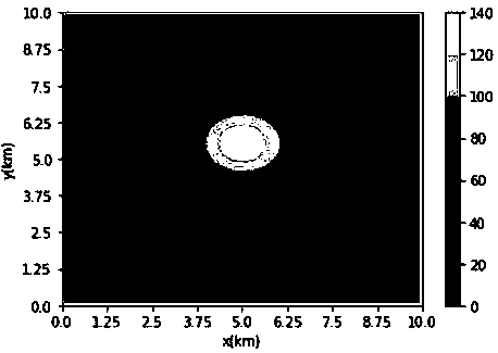
[0078] The three-dimensional combined model is used to test the inversion effect of the method. The subdivision range of the underground half space is x direction: 0~9240 meters, y direction: 0~9240 meters, z direction: 0: 3040 meters, and each direction is divided into 10 grid, set two geological bodies, the density of geological body 1 is 1.0g / cm 3 , the distribution grid is x direction: 4~6, y direction: 3~5, z direction 2~4, the density of geological body 2 is 3.0g / cm 3 , the distribution grid is x direction: 4~6, y direction: 4~6, z direction 5~7, observation system range x direction: 0~10000 meters, y direction 0~1000 meters, observation point height is 0 meters, The distance between observation points in each direction is 500 meters, and there are 400 observation points in total. The model and simulated observation data are as follows: image 3 and Figure 4 shown. ...


PUM


Abstract

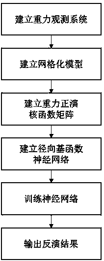
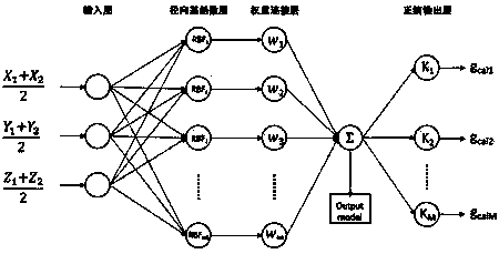
The invention provides a gravity field density inversion method based on a quasi-radial basis function neural network. The method comprises a step of establishing a gravity observation system, a stepof establishing a gridded model, a step of establishing a gravity forward kernel function matrix, a step of establishing a radial basis function neural network, a step of training the neural network,and a step of outputting an inversion result. According to the method, a model space is compressed by using a radial basis function, and the dimensionality reduction of inversion parameters is achieved under the premise of ensuring complex model representation ability. A pseudo-neural network structure is proposed, the training of a sample tag is not needed, the difficulty of establishing a training data set is avoided, and a gravity field density inversion algorithm is achieved based on the pseudo-neural network structure. The vertical resolution and reliability of an inversion result are improved, the method has strong anti-noise ability, and the application field of a gravity inversion method is extended.

Description

technical field [0001] The invention belongs to the field of geophysical inversion, and specifically refers to a gravity inversion method, in particular to a method for inverting an underground target density model based on a quasi-radial basis function neural network using gravity field data. Background technique [0002] Gravity prospecting is widely used in regional geological surveys, basin framework studies, and deep and large fault reconnaissance because of its fast data collection and low price. It restricts its application in high-precision exploration fields, such as oil and gas exploration. The root cause of the above problems lies in the ill-posed nature of the inverse gravity problem. First, the density of gravity data collection is low and the amount of data is small, while high-resolution inversion requires high-density subdivision of the underground half-space, making the number of unknown parameters in the inversion far greater than the number of data, resul...

Claims


Application Information

Patent Timeline
Patent Type & Authority Patents(China)
IPC IPC(8): G01V7/06
CPCG01V7/06
Inventor 相鹏刘佳陈学国王金铎于会臻谭绍泉王有涛张建华杨国杰王月蕾
Owner CHINA PETROLEUM & CHEM CORP
Learn More