Fixed-focus optical system

An optical system, negative optical power technology, applied in the field of optical systems, can solve the problems of long length, unfavorable lens miniaturization requirements, etc., and achieve the effects of low temperature drift, temperature drift, and high resolution

Pending Publication Date: 2018-09-04
NINGBO YONGXIN OPTICS
View PDF0 Cites 13 Cited by
  • Summary
  • Abstract
  • Description
  • Claims
  • Application Information

AI Technical Summary

Problems solved by technology

However, the length of the existing wide-angle lens is large, which is not conducive to the miniaturization requirements of the lens

Method used


Image

  • Fixed-focus optical system
  • Fixed-focus optical system
  • Fixed-focus optical system

Examples


Embodiment 1

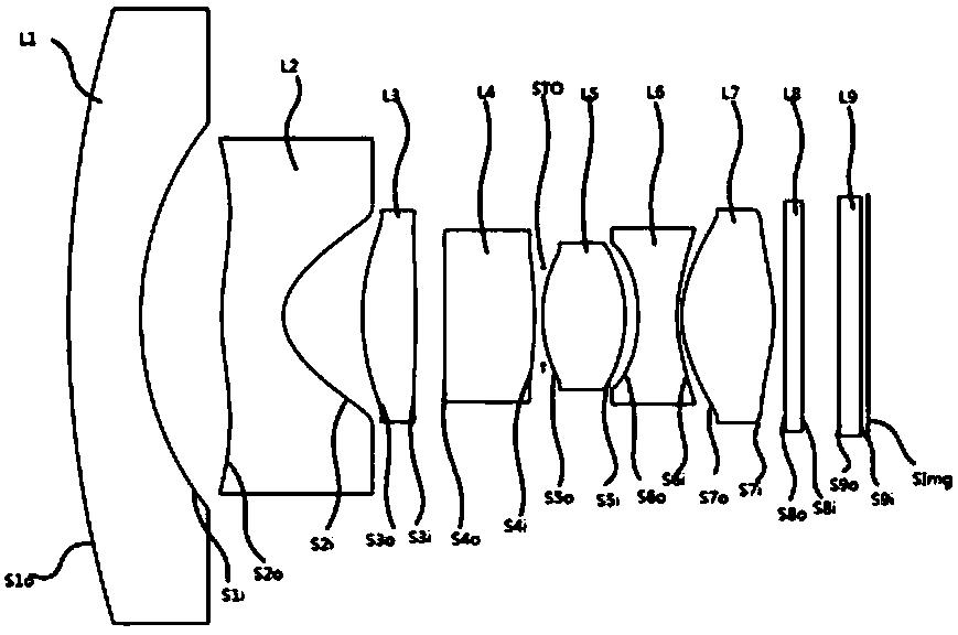
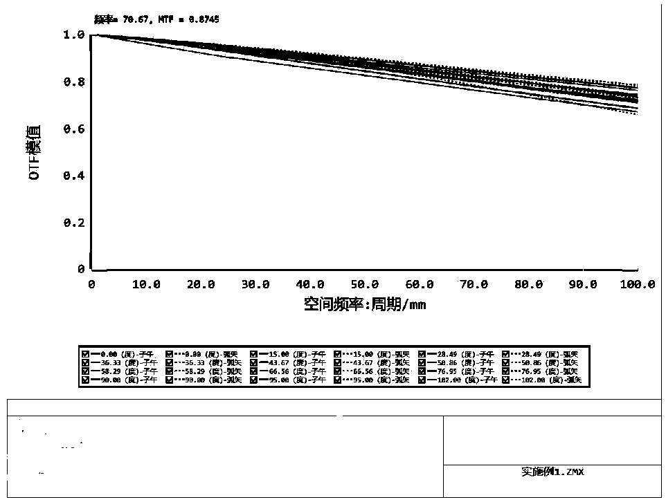
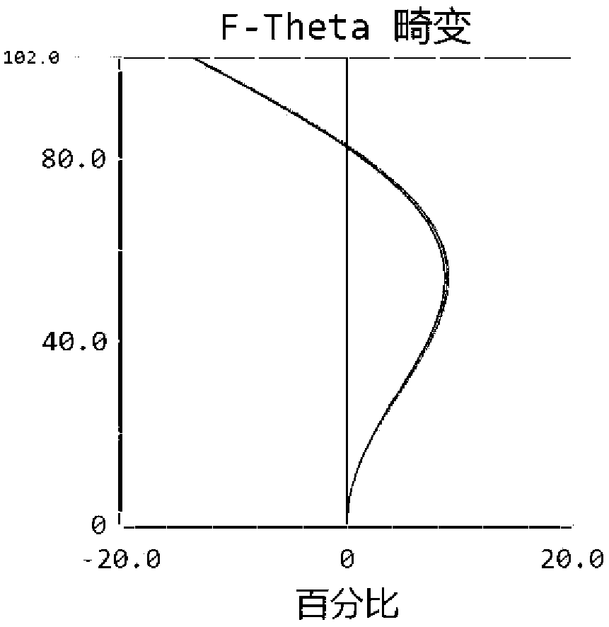
[0030] Reference attachment for the seven-piece fixed-focus optical system of this embodiment figure 1 . From the object side to the image side, a first lens L1 with negative refractive power, a second lens L2 with negative refractive power, a third lens L3 with positive refractive power, and a fourth lens with positive refractive power are arranged in order from the object side to the image side. L4, aperture stop STO, fifth lens L5 with positive refractive power, sixth lens L6 with negative refractive power, seventh lens L7 with positive refractive power, filter L8, chip protection glass L9.

[0031] Among them: L1 is the convex surface of the object side S1o, the negative lens of the image side S1i concave surface, the focal length is f1, L2 is the central convex surface of the object side S2o, the negative lens of the concave surface of the image side S2i, the focal length is f2, L3 is the object side S3o and the image side S3i All are convex positive lenses, focal length is ...

Embodiment 2

[0047] Reference attachment for the seven-piece fixed-focus optical system described in this embodiment Figure 5 .From the object side to the image side are arranged in sequence: a first lens L1 with negative refractive power, a second lens L2 with negative refractive power, a third lens L3 with positive refractive power, and a fourth lens with positive refractive power. Lens L4, aperture stop STO, fifth lens L5 with positive refractive power, sixth lens L6 with negative refractive power, seventh lens L7 with positive refractive power, filter L8, chip protection glass L9.

[0048] Among them: L1 is the convex surface of the object side S1o, the negative lens of the image side S1i concave surface, the focal length is f1, L2 is the central convex surface of the object side S2o, the negative lens of the concave surface of the image side S2i, the focal length is f2, L3 is the object side S3o and the image side S3i All are convex positive lenses, the focal length is f3, L4 is the conv...

Embodiment 3

[0061] Reference attachment for the seven-piece fixed-focus optical system described in this embodiment Picture 9 . From the object side to the image side are arranged in sequence: a first lens L1 with negative refractive power, a second lens L2 with negative refractive power, a third lens L3 with positive refractive power, a second lens with negative refractive power Four lens L4, aperture stop STO, fifth lens L5 with positive refractive power, sixth lens L6 with negative refractive power, seventh lens L7 with positive refractive power, filter L8, chip protection glass L9.

[0062] Among them: L1 is the convex surface of the object side S1o, the negative lens of the image side S1i concave surface, the focal length is f1, L2 is the central convex surface of the object side S2o, the negative lens of the concave surface of the image side S2i, the focal length is f2, L3 is the object side S3o and the image side S3i All are convex positive lenses with focal length f3, L4 is concave o...


PUM


Abstract

The invention discloses a fixed-focus optical system which successively comprises seven lenses from the object side to the image side, wherein the first lens is provided with negative power, a objectside convex surface and an image side convex surface; the second lens is provided with negative power, a object side convex surface and an image side convex surface; the third lens is provided with positive power and double convex surfaces; the image side surface of the fourth lens is a convex surface, when the focal power is positive, C4o is greater than or equal to 0, and the C4o is the curvature of the object side face of the fourth lens; when the focal power is negative, the object side face of the fourth lens is a concave surface; the fifth lens is provided with positive power and doubleconvex surfaces; the sixth lens is provided with negative powder and two concave surfaces; the seventh lens is provided with positive power and double convex surfaces; and the relationship is met: Imeg/f is greater than 1.28 but less than 2.22, and Imeg/TTL is greater than 0.105 but less than 0.167, wherein Imeg is the highest half image height, TTL is the axis distance from the object side face of the first lens to the image side face, and f is system focal distance. The system has the advantages that the power is reasonably matched; by means of reasonable parameter matching, a miniature optical system design which is high in resolution, good in image quality and low in cost is achieved.

Description

Technical field [0001] The invention relates to an optical system, in particular to a fixed-focus optical system that can be applied in the field of vehicle-mounted or monitoring. Background technique [0002] With the rapid development of social economy and technology, vehicle imaging and security monitoring systems have become more and more popular and high-end. And as the semiconductor manufacturing process becomes more mature, the pixel size of the chip is getting smaller and smaller and more compact. The demand for high-resolution imaging systems is increasing. [0003] Because the wide-angle system has a large field of view, one image acquisition can achieve more information. Therefore, the wide-angle system has great advantages in the field of vehicle surround view and large field of view monitoring. A general wide-angle lens uses 5 or more lenses to achieve a wide-angle effect, and the maximum field of view of a general wide-angle system is about 180 degrees. However, t...

Claims


Application Information

Patent Timeline
Patent Type & Authority Applications(China)
IPC IPC(8): G02B13/00G02B13/06G02B13/18
CPCG02B13/0045G02B13/06G02B13/18
Inventor 张丽芝毛磊齐洋杨勇
Owner NINGBO YONGXIN OPTICS
Why Eureka
Try Eureka