Multifunctional microcomputer monitoring and protection device and using method thereof

A monitoring protection and monitoring device technology, which is applied in the direction of circuit devices, cooling/ventilation of substation/switchgear, details of substation/switch layout, etc., can solve the problems of reducing the service life of the device, large switch cabinet size, inconvenient movement, etc., to achieve Firm and convenient installation, convenient disassembly and installation, good protection effect

Inactive Publication Date: 2018-09-04
安徽方瑞电气科技有限公司
View PDF5 Cites 4 Cited by
  • Summary
  • Abstract
  • Description
  • Claims
  • Application Information

AI Technical Summary

Problems solved by technology

[0002] At present, microcomputer monitoring and protection devices have powerful functions such as protection device operation, data display, and monitoring operation, and are widely used in petroleum, chemical, electric power, coal and other industries. Most of the microcomputer monitoring and protection devices are installed in switch cabinets. The switchgear is large and inconvenient to move, and it is impossible to monitor the working temperature of the device at any time, which limits the scope of use of the microcomputer monitoring and protection device to indoors, reduces the service life of the device, and makes the space occupied by the microcomputer monitoring and protection device more efficient. less than fully utilized
[0003] The disassembly and installation of the microcomputer monitoring and protection device is inconvenient, and it is also difficult to assemble and install itself, and it does not have a heat dissipation function

Method used


Image

  • Multifunctional microcomputer monitoring and protection device and using method thereof
  • Multifunctional microcomputer monitoring and protection device and using method thereof
  • Multifunctional microcomputer monitoring and protection device and using method thereof

Examples


Embodiment Construction

[0020] The following will clearly and completely describe the technical solutions in the embodiments of the present invention with reference to the accompanying drawings in the embodiments of the present invention. Obviously, the described embodiments are only some, not all, embodiments of the present invention. Based on the embodiments of the present invention, all other embodiments obtained by persons of ordinary skill in the art without making creative efforts belong to the protection scope of the present invention.

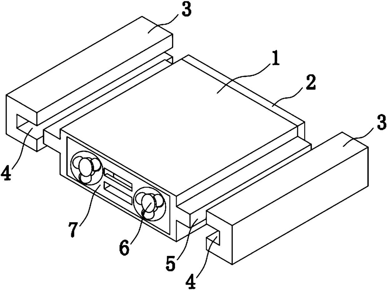
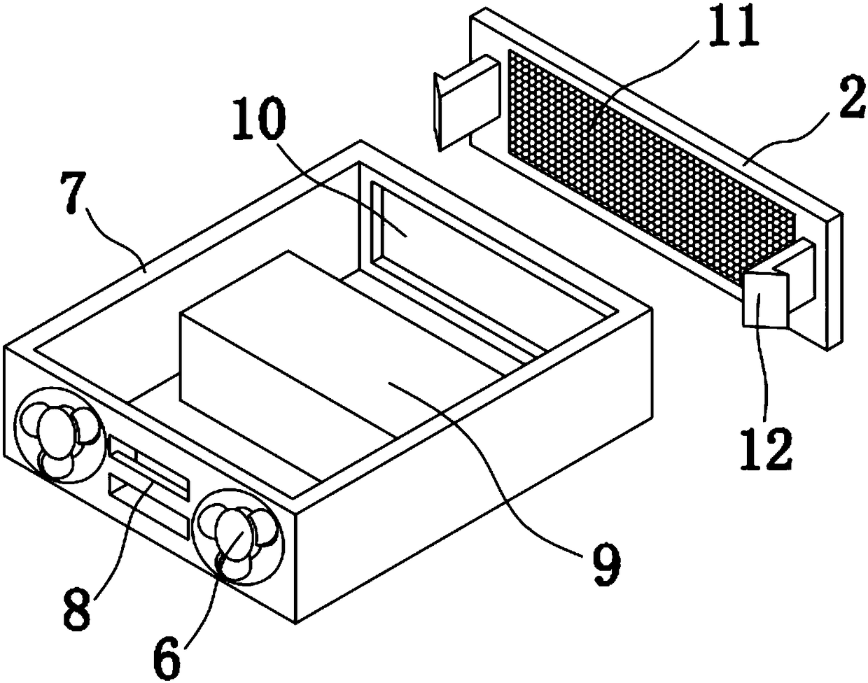
[0021] The present invention provides such Figure 1-3 A multi-functional microcomputer monitoring and protection device, comprising a hollow rectangular protective shell 1, the rear of the rectangular protective shell 1 is equipped with an air intake protection plate 2, and the rectangular protective shell 1 is plugged with Rectangular drawer housing 7, heat dissipation fans 6 are installed on the left and right sides of the front part of the rectangular draw...


PUM


Abstract

The invention discloses a multifunctional microcomputer monitoring and protection device comprising a hollow rectangular protective shell; and an air-suction protection plate is installed behind the rectangular protective shell. A rectangular drawer case is inserted into the rectangular protective shell; cooling fans are installed at the left side and right side of the front of the rectangular drawer case; and a microcomputer monitoring device is arranged inside the rectangular drawer case. A filter mesh is arranged in the middle of the air-suction protection plate; and buckles extend into a rectangular opening slot and are clamped at the left inner side and the right inner side of the rectangular opening slot. According to the invention, the rectangular drawer case is dismounted or mounted conveniently; and because the buckles arranged at the two sides of the rear of the air-suction protection plate extend into the rectangular opening slot and are clamped at the left inner side and the right inner side of the rectangular opening slot, the rectangular drawer case, the air-suction protection plate, and the rectangular protective shell are fixed without any bolt and the assembling and installation become firm and conveniently, so that the microcomputer monitoring device is protected well.

Description

technical field [0001] The invention belongs to the technical field of multifunctional microcomputer monitoring and protection devices, in particular relates to a multifunctional microcomputer monitoring and protection device, and also relates to a method for using the multifunctional microcomputer monitoring and protection device. Background technique [0002] At present, microcomputer monitoring and protection devices have powerful functions such as protection device operation, data display, and monitoring operation, and are widely used in petroleum, chemical, electric power, coal and other industries. Most of the microcomputer monitoring and protection devices are installed in switch cabinets. The switchgear is large and inconvenient to move, and it is impossible to monitor the working temperature of the device at any time, which limits the scope of use of the microcomputer monitoring and protection device to indoors, reduces the service life of the device, and makes the s...

Claims


Application Information

Patent Timeline
Patent Type & Authority Applications(China)
IPC IPC(8): H02B1/36H02B1/56H02J13/00
CPCH02B1/36H02B1/565H02J13/0075Y02B90/20Y04S40/126
Inventor 周进军戴亮冬施昌平
Owner 安徽方瑞电气科技有限公司
Why Eureka
Try Eureka