Method and system for flexible direct current back-to-back device placement and capacity allocation

A flexible DC and capacity allocation technology, applied in the field of power transmission, to achieve the effects of less communication interference, optimized cross-section power flow distribution, and low overall cost

Active Publication Date: 2021-06-15
CHINA ELECTRIC POWER RES INST +2
View PDF0 Cites 0 Cited by
  • Summary
  • Abstract
  • Description
  • Claims
  • Application Information

AI Technical Summary

Problems solved by technology

[0006] The present invention provides a method and system applied to the selection of the landing point and capacity configuration of the flexible DC back-to-back device to solve the problem of how to select the landing point and configure the capacity of the flexible DC back-to-back device

Method used


Image

  • Method and system for flexible direct current back-to-back device placement and capacity allocation
  • Method and system for flexible direct current back-to-back device placement and capacity allocation
  • Method and system for flexible direct current back-to-back device placement and capacity allocation

Examples


Embodiment Construction

[0061] Exemplary embodiments of the present invention will now be described with reference to the drawings; however, the present invention may be embodied in many different forms and are not limited to the embodiments described herein, which are provided for the purpose of exhaustively and completely disclosing the present invention. invention and fully convey the scope of the invention to those skilled in the art. The terms used in the exemplary embodiments shown in the drawings do not limit the present invention. In the figures, the same units / elements are given the same reference numerals.

[0062] Unless otherwise specified, the terms (including scientific and technical terms) used herein have the commonly understood meanings to those skilled in the art. In addition, it can be understood that terms defined by commonly used dictionaries should be understood to have consistent meanings in the context of their related fields, and should not be understood as idealized or over...


PUM


Abstract

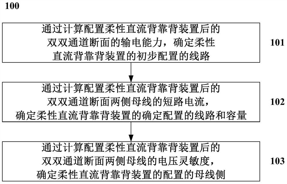
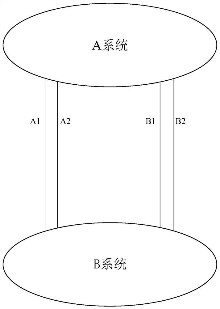
The invention discloses a method applied to the placement selection and capacity configuration of a flexible DC back-to-back device. The method includes: determining the power transmission capacity of the flexible DC back-to-back device by calculating the power transmission capability of the dual-channel cross-section after the flexible DC back-to-back device is configured. Preliminarily configured circuit; by calculating the short-circuit current of the busbars on both sides of the double-channel cross-section after the flexible DC back-to-back device is configured, the circuit and capacity of the determined configuration of the flexible DC back-to-back device are determined; by calculating the double dual-channel after the flexible DC back-to-back device is configured The voltage sensitivity of the busbars on both sides of the section determines the busbar side of the configuration of the flexible DC back-to-back device. By building a new flexible DC back-to-back device at the busbar on one side of a double-circuit line of an existing double-circuit line section, the power flow distribution of the section can be optimized, the overall transmission capacity of the section can be improved, and the short-circuit current of the busbars on both sides of the section can be reduced, providing auxiliary voltage reactive power support ability.

Description

technical field [0001] The present invention relates to the technical field of power transmission, and more specifically, relates to a method and system applied to landing point selection and capacity configuration of a flexible DC back-to-back device. Background technique [0002] With the rapid development of the power system, the transmission power demand of the existing 500kV line section is getting higher and higher, and it is getting closer to its thermal stability limit. The power grid structure on both sides of the transmission section is relatively dense, and the short-circuit current level of the busbar is relatively high. If the conventional scheme of building a new tie line is adopted, the short-circuit current of the busbars on both sides may exceed the standard. In addition, some sections, such as cross-river cross-river sections, are difficult to construct, and it is impossible to increase the power transmission capacity of the section by adding AC transmissi...

Claims


Application Information

Patent Timeline
Patent Type & Authority Patents(China)
IPC IPC(8): H02J3/36
CPCH02J3/36Y02E60/60
Inventor 唐晓骏谢岩王璟张正卫张晓东申旭辉郭长辉张鑫田春筝程鑫罗红梅张振安饶宇飞刘建勋李晶李晓珺宋少群司瑞华李程昊霍启迪吉平李媛媛李再华李立新张恺
Owner CHINA ELECTRIC POWER RES INST
Why Eureka
Try Eureka