
Fire fighting truck

A technology for fire trucks and locomotives, applied in fire rescue and other directions, can solve problems such as difficult operation, difficult to adjust the direction of entry and exit, and inconvenient firefighting work.

Active Publication Date: 2018-09-07
日照新睿招商发展有限公司
View PDF5 Cites 2 Cited by
  • Summary
  • Abstract
  • Description
  • Claims
  • Application Information

AI Technical Summary

Problems solved by technology

[0004] The purpose of the present invention is to provide a kind of fire engine, to solve the existing fire engine proposed in the above-mentioned background technology, when arriving at a narrow destination, it is difficult to adjust the direction of entry and exit, which brings inconvenience to the fire fighting work, and the structure is complicated and difficult to operate. The difficulty is high, which reduces the efficiency of firefighting work and affects people's lives and safety

Method used


Image

  • Fire fighting truck
  • Fire fighting truck
  • Fire fighting truck

Examples


Embodiment 1

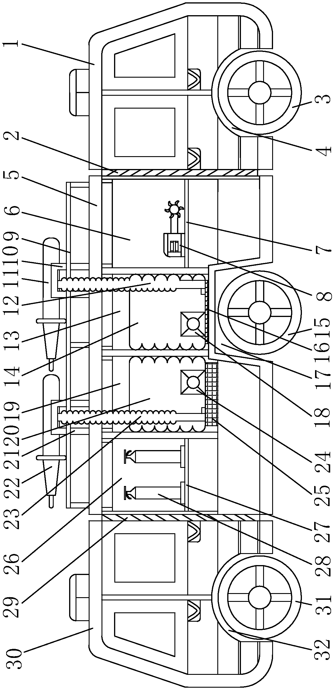
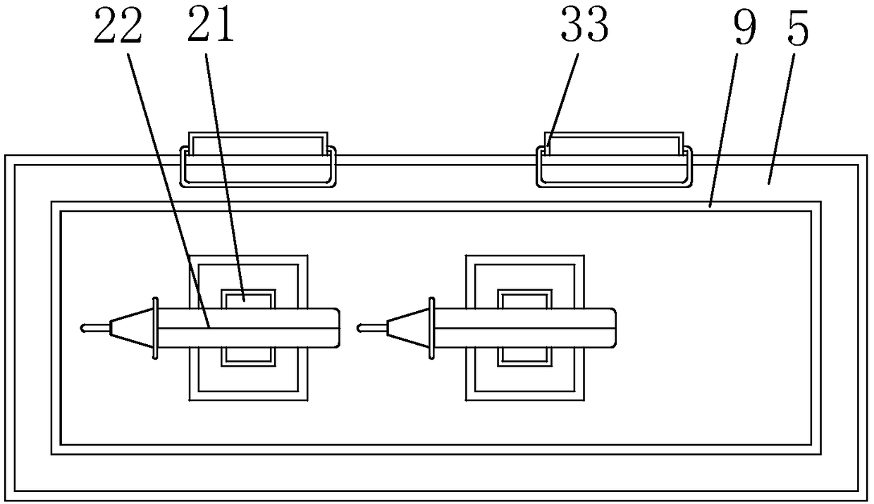
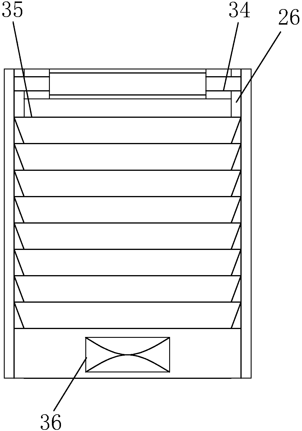
[0045] see Figure 1-3 , the present invention provides a technical solution: a fire truck, including a first front shell 1, a first junction 2, a first wheel 3, a first chamber 4, a body shell 5, a first storage chamber 6, a first Support plate 7, cutting machine 8, fence 9, first lifting column 10, first high-pressure water gun 11, first outlet pipe 12, second storage chamber 13, first water tank 14, second wheel 15, first buffer pad 16 , the second chamber 17, the first water pump 18, the third storage chamber 19, the second water tank 20, the second lifting column 21, the second high-pressure water gun 22, the second outlet pipe 23, the second water pump 24, the second cushion 25. The fourth storage chamber 26, the second support plate 27, the fire tank 28, the second junction 29, the second front shell 30, the third wheel 31, the third chamber 32, the climbing ladder 33, the rotating shaft 34, Sheet-shaped sliding door 35 and push-pull block 36, the bottom of the first h...

Embodiment 2

[0048] see Figure 4-9 , this embodiment also includes the following features on the basis of Embodiment 1: the first water tank and the second water tank are respectively connected with filter pumps through pipelines; the filter pumps are used to draw water from wells, rivers or lakes.

[0049] The filter pump includes a motor 91 , a pump casing 92 and a water wheel 96 rotatably installed in the pump casing and driven by the motor.

[0050] A pump cover 911 is connected to the lower end of the motor, and the pump cover is sealingly connected to the upper end of the pump casing with an open upper end, and a pump chamber is formed between the pump casing and the pump cover.

[0051] The middle of the lower end of the pump housing is integrally connected with a circular pipe-shaped water inlet pipe portion 921 , and the side wall of the pump housing is integrally connected with a water outlet joint 923 .

[0052] In the middle of the lower end of the motor is a polygonal drive ...


PUM


Abstract

The invention relates to a fire fighting truck, which comprises a first truck head case, a first connecting position, a first storage chamber, a first ascending and descending post, a first water pump, a climbing ladder and a flaky sliding door, wherein the bottom of the first truck head case is provided with a first cavity ; in addition, a first wheel is arranged at the inner side of the first cavity; the first connecting position is connected with the left end of the first truck head case; the left side of the first connecting position is fixedly provided with a truck body case; the first storage chamber is arranged inside the truck body case; the top end of the truck body case is provided with a fence pipe. The fire fighting truck has the beneficial effects that through the arrangementof the first truck head case, the first wheel, a second wheel and a third wheel, the fire fighting truck can be driven to forwards run to the fire hazard sites through the rolling of the wheels; whenthe fast reversing is needed in narrow places, the reversing driving operation can be completed through the effects of the second truck head case and the wheels.

Description

technical field [0001] The invention relates to the technical field of fire fighting, in particular to a fire truck. Background technique [0002] With the development of science and technology and the progress of the social era, fires often occur around us, and the fire is very harmful. It is necessary to call the police in time and ask for help from firefighters. The fire trucks used by firefighters in firefighting work are also called fire engines. Refers to special vehicles that are mainly used to perform fire response tasks. The fire departments of most countries including China will also use them for other emergency rescue purposes. Fire trucks can transport firefighters to disaster sites and provide them with disaster relief tasks. Various tools. [0003] When the existing fire trucks arrive at a narrow destination, it is difficult to adjust the direction of entry and exit, which brings inconvenience to the firefighting work, and the structure is complex and difficul...

Claims


Application Information

Patent Timeline
Patent Type & Authority Applications(China)
IPC IPC(8): A62C27/00
CPCA62C27/00
Inventor 李为松其他发明人请求不公开姓名
Owner 日照新睿招商发展有限公司
Learn More