Intermittent material cutting machine

A material cutting machine, L-shaped technology, applied in the direction of metal processing machinery parts, driving devices, metal processing equipment, etc., can solve the problems of high cost of use, increased unknown risks, and difficult loading and unloading processes

Inactive Publication Date: 2018-09-07
WUHU TIANMENG INFORMATION TECH CO LTD
View PDF5 Cites 4 Cited by
  • Summary
  • Abstract
  • Description
  • Claims
  • Application Information

AI Technical Summary

Problems solved by technology

[0002] Among the existing cutting machines, many of them are disc-shaped and perform one-way circular motion. Although the cutting efficiency is very high, the continuous movement without gaps will increase the unknown risks of the entire cutting process and make the loading and unloading process more difficult. It is more difficult, and often requires a hydraulic device to move the cutting disc up and down, which makes the whole device more bulky, and increases the consumption and use cost, so a cutting device with simple operation and simple equipment is needed

Method used


Image

  • Intermittent material cutting machine
  • Intermittent material cutting machine
  • Intermittent material cutting machine

Examples


Embodiment Construction

[0015] Preferred embodiments of the present invention will be described in detail below in conjunction with the accompanying drawings.

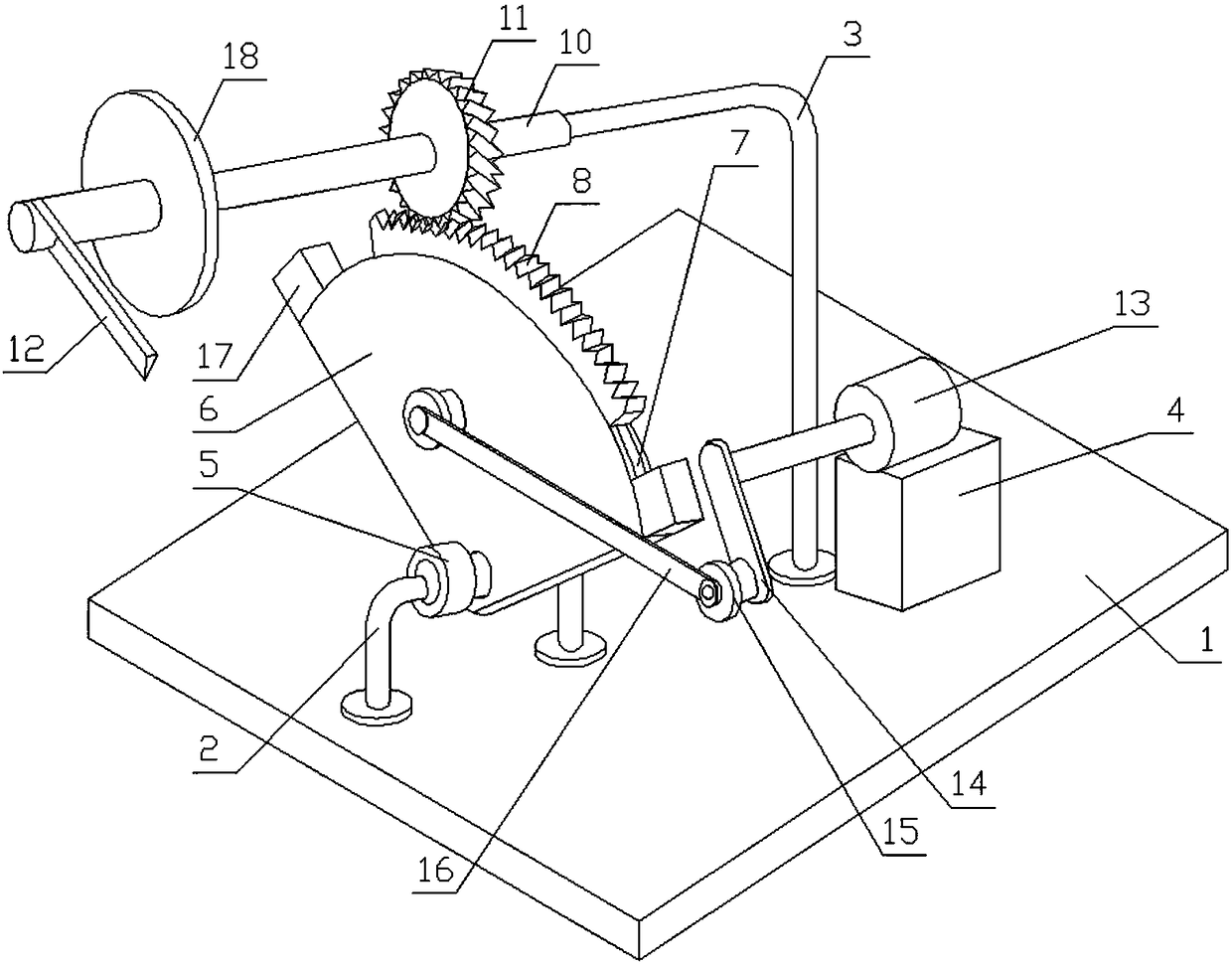
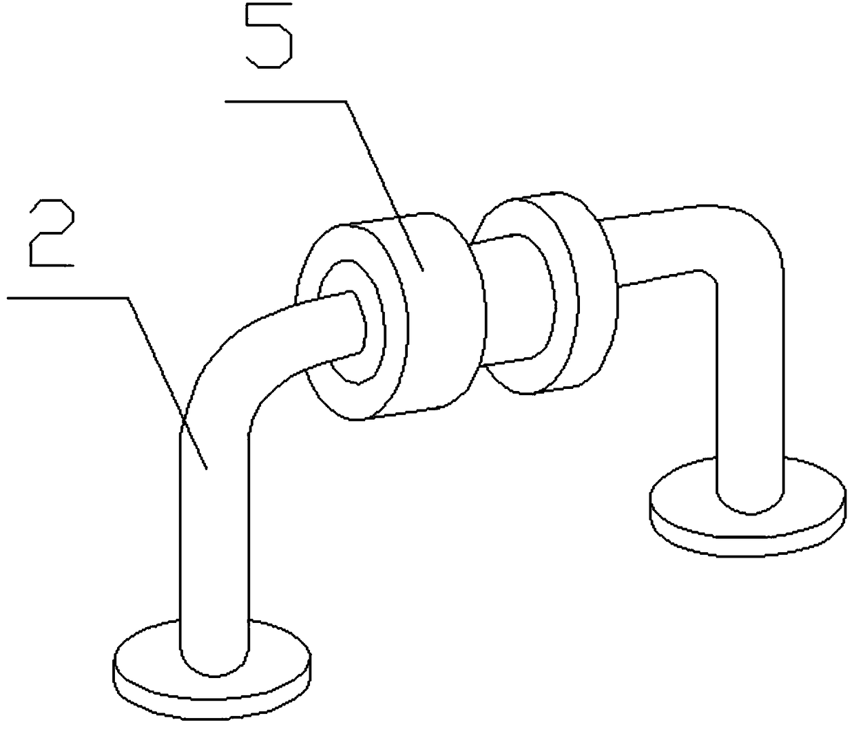
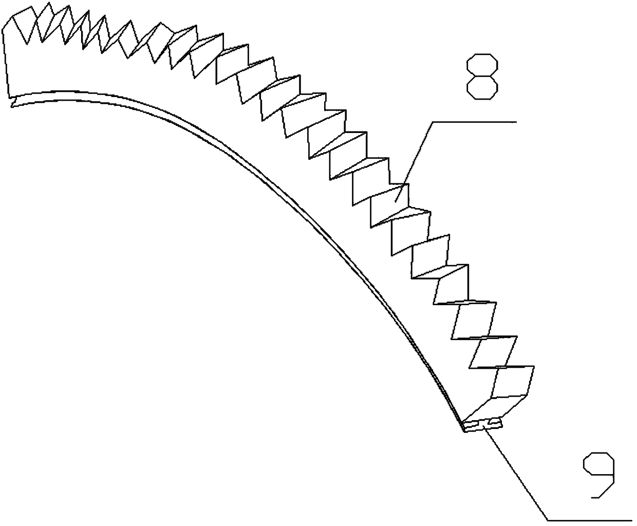
[0016] Figure 1-4 A preferred embodiment of the present invention is described in detail below in conjunction with an intermittent cutting machine, including a base plate 1, a C-shaped bracket 2, an L-shaped bracket 3 and a mounting seat 4, and the C-shaped bracket 2, the L-shaped bracket 3 and the installation The seat 4 is arranged on the base, and the C-shaped bracket 2 is provided with an I-shaped rotating seat 5, and the I-shaped rotating seat 5 is rotated with a fan-shaped turntable 6, and the arc surface of the fan-shaped turntable 6 is provided with T-shaped chute 7, arc-shaped rack 8 is provided on the arc surface of the fan-shaped turntable 6, and a T-shaped slider 9 is provided at the bottom of the arc-shaped rack 8, and the T-shaped slider 9 is slidably arranged on T In the type chute 7, the front end of the L-shaped support 3 i...


PUM


Abstract

The invention discloses an intermittent material cutting machine comprising a bottom plate, a C-shaped bracket, an L-shaped bracket and a mounting seat. The C-shaped bracket, the L-shaped bracket andthe mounting seat are arranged on a base, the C-shaped bracket is provided with an I-shaped rotating seat, the I-shaped rotating seat is rotatably provided with a fan-shaped rotating disc, and a T-shaped sliding groove is formed in the arc surface of the fan-shaped rotating disc; an arc-shaped rack is arranged on the arc surface of the fan-shaped rotating disc, a T-shaped sliding block is arrangedat the bottom of the arc-shaped rack, the T-shaped sliding block is slidably arranged in the T-shaped sliding groove, a hollow rotating shaft is arranged at the front end of the L-shaped bracket in asleeving mode, and a gear and a cutting blade are fixedly arranged on the hollow rotating shaft; a rotating motor is arranged on the mounting seat, an output shaft of the rotating motor is provided with a rotating plate, mounting columns are fixedly arranged at the tail end of the rotating plate and the center of the fan-shaped rotating disc, a long-strip transmission plate is arranged between the two mounting columns, and the two ends of the transmission plate are rotatably connected with the two mounting columns. According to the intermittent material cutting machine, certain stopping timeis left at the conversion interval of driving the cutting blade to rotate in a reciprocating mode, and feeding and discharging once more are convenient.

Description

technical field [0001] The invention relates to the technical field of cutting devices, in particular to an intermittent cutting machine. Background technique [0002] Among the existing cutting machines, many of them are disc-shaped and perform one-way circular motion. Although the cutting efficiency is very high, the continuous movement without gaps will increase the unknown risks of the entire cutting process and make the loading and unloading process more difficult. It is more difficult, and often requires a hydraulic device to move the cutting disc up and down, which makes the whole device more bulky, and increases the consumption and use cost, so a cutting device with simple operation and simple equipment is needed. Contents of the invention [0003] The technical problem to be solved by the present invention is to provide an intermittent cutting machine to solve the above-mentioned multiple defects caused in the prior art. [0004] In order to achieve the above obj...

Claims


Application Information

Patent Timeline
Patent Type & Authority Applications(China)
IPC IPC(8): B23D79/00B23Q5/10
CPCB23D79/00B23Q5/10
Inventor 徐忠张贵平
Owner WUHU TIANMENG INFORMATION TECH CO LTD
Why Eureka
Try Eureka