Aeroelastic model testing device based on gas rigidity

An aeroelastic model and test device technology, which is applied in the direction of aerodynamic test, measuring device, machine/structural component testing, etc., can solve the problems of difficult debugging and low stiffness adjustment accuracy, and achieve good shape applicability and rigidity. Easy-to-adjust, easy-to-make effects

Active Publication Date: 2018-09-07
GUANGZHOU UNIVERSITY
View PDF13 Cites 2 Cited by
  • Summary
  • Abstract
  • Description
  • Claims
  • Application Information

AI Technical Summary

Problems solved by technology

However, the aeroelastic models currently used by most scholars have problems such as low stiffness adjustment accuracy or difficult debugging.

Method used


Image

  • Aeroelastic model testing device based on gas rigidity
  • Aeroelastic model testing device based on gas rigidity
  • Aeroelastic model testing device based on gas rigidity

Examples


Embodiment

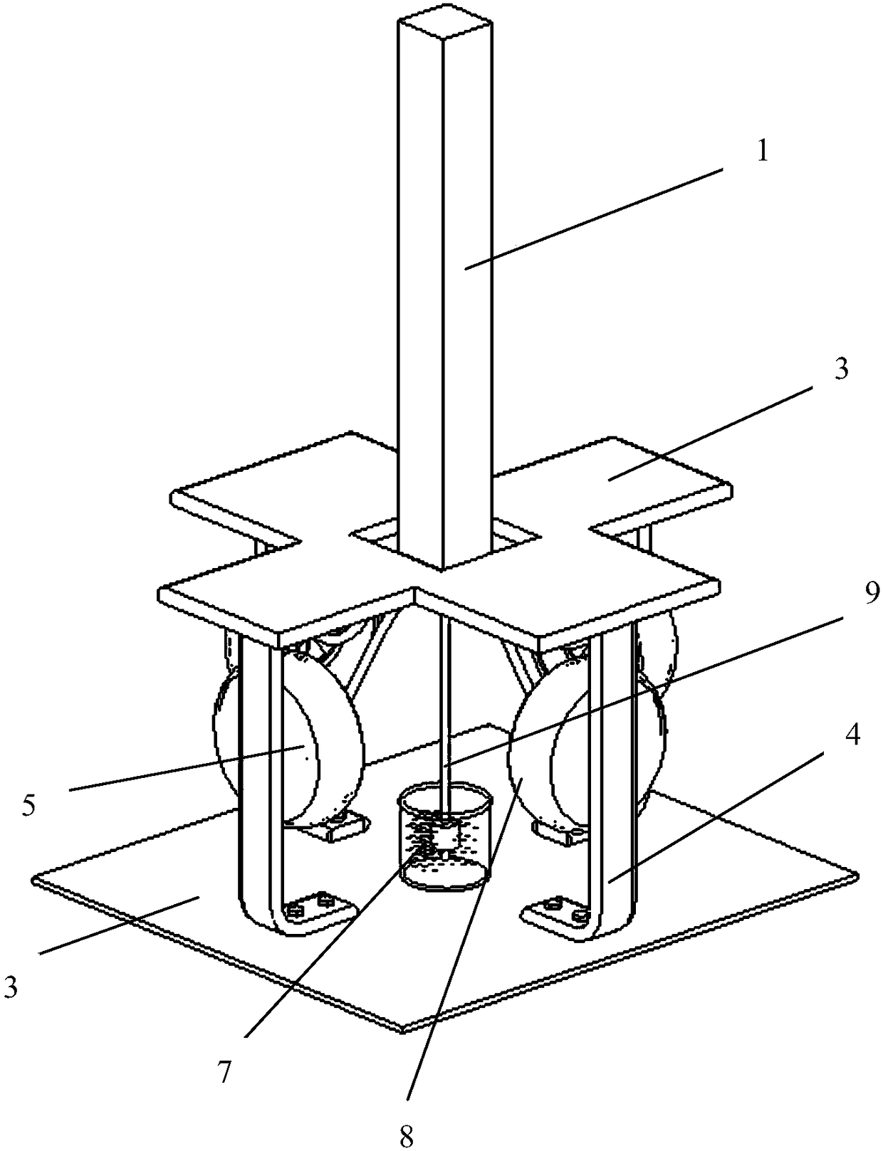
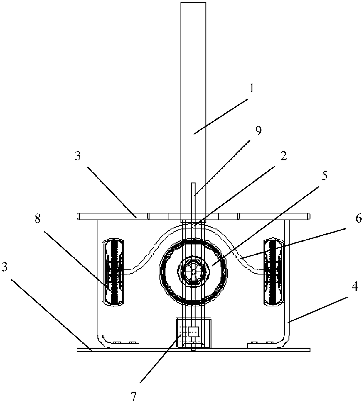
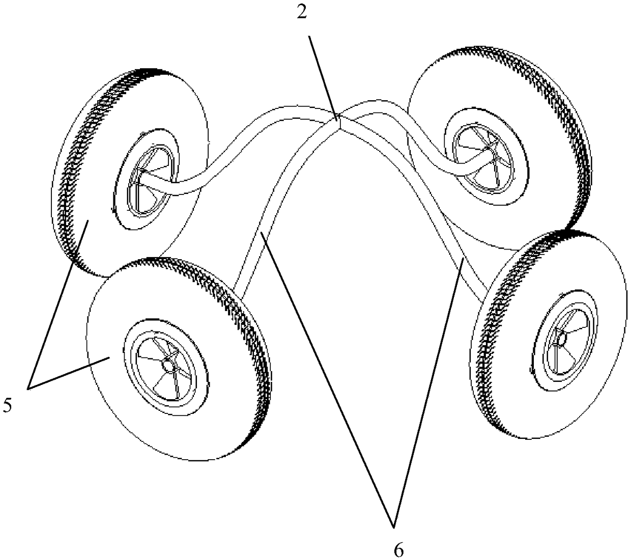
[0022] In the elastic range, the stiffness is the external force required for the unit displacement deformation of the measured object, that is, the force required to cause the unit displacement. This patent changes the "air stiffness" of the tire by inflating the tire of the aeroelastic test model, thereby continuously Accurately change the stiffness of the aeroelastic test model. The specific realization process is: Inflate the tire according to the test conditions. The tire will slightly expand and become hard due to inflation. When the test model rotates in the X and Y directions, it will squeeze against the fixed annular wall, so the annular wall will A reaction force is generated on the tire. In this way, the force required for the aeroelastic test model to produce a unit displacement will increase, and the stiffness of the aeroelastic test model will change.

[0023] Such as figure 1 , 2 As shown, the aeroelastic model test device based on aerodynamic stiffness of the pre...


PUM


Abstract

The invention belongs to the field of aerodynamic wind tunnel tests in wind engineering and relates to an aeroelastic model testing device based on gas rigidity. The aeroelastic model testing device comprises a testing model, a fixing device, two vertically vertical shafts, four inflatable annular tires and a tire pressure monitoring system, wherein the fixing device comprises a base plate, at least four cantilevers and a connecting rod, the cantilevers are fixedly connected between an upper base plate and a lower base plate, one end of the connecting rod is fixed on the lower base plate, andthe other end of the connecting rod is inserted into the testing model through the two mutually vertical shafts; the tail ends of the two mutually vertical shafts are connected with the four inflatable annular tires and are fixed in a space formed by the upper base plate, the lower base plate and the cantilevers; and the inflatable annular tires are located on the inner sides of the cantilevers and are in contact with the inner sides of the cantilevers after being inflated; and the tire pressure monitoring system is connected with the inflatable annular tires. According to the aeroelastic model testing device, the rigidity of the model can be continuously, accurately and conveniently changed, and the structure of the aeroelastic model testing device is simple.

Description

Technical field [0001] The invention belongs to the field of aerodynamic wind tunnel test in wind engineering, and specifically relates to an aeroelastic model test device based on aerodynamic stiffness. Background technique [0002] With the rapid development of economy and society, large-scale towering structures such as high-rise / super high-rise buildings have appeared in large numbers. These buildings are very sensitive to wind loads due to their high height and flexibility; therefore, in order to ensure the safety, reliability and comfort of these flexible structures, wind tunnel tests are generally required to evaluate the wind effects of the buildings. Traditional building model wind tunnel tests include three types: multi-point transient wind pressure synchronous measurement model test (hereinafter referred to as pressure test), high-frequency dynamic balance test (referred to as force test) and aeroelastic model test (referred to as aeroelastic test) ). Compared with t...

Claims


Application Information

Patent Timeline
Patent Type & Authority Applications(China)
IPC IPC(8): G01M9/04
CPCG01M9/04Y02T90/00
Inventor 何运成李智梁启胜傅继阳吴玖荣
Owner GUANGZHOU UNIVERSITY
Why Eureka
Try Eureka