Circuit breaker with arc shield

A circuit interrupter, arc technology, applied in circuit breaker parts, circuits, circuit breaker contacts, etc., can solve problems such as negative effects on the system

Active Publication Date: 2018-09-07
CARLING TECH
View PDF6 Cites 1 Cited by
  • Summary
  • Abstract
  • Description
  • Claims
  • Application Information

AI Technical Summary

Problems solved by technology

Even a slight delay in opening the contacts can have a very large negative impact on the system

Method used


Image

  • Circuit breaker with arc shield
  • Circuit breaker with arc shield
  • Circuit breaker with arc shield

Examples


Embodiment Construction

[0041] It is found with reference to the drawings, wherein like reference numerals designate corresponding structures throughout the views.

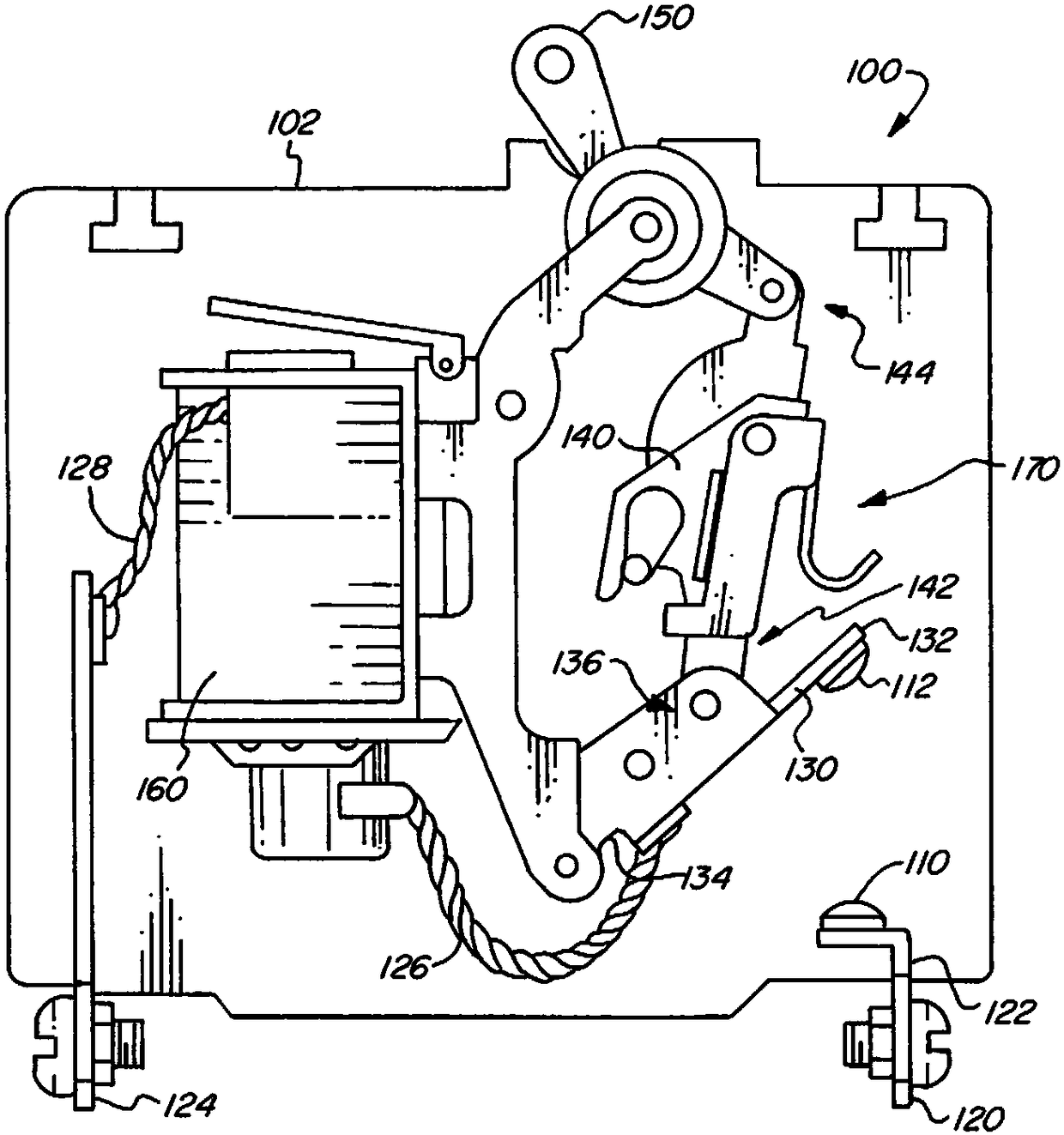
[0042] figure 1 Several components of an example circuit interrupter 100 are shown in accordance with aspects of the present invention.

[0043] Circuit interrupter 100 may be any device that can be used to make and break electrical circuits using contacts. For example, circuit interrupter 100 may be a simple switch, or a circuit breaker having housing 102, for example, as will be apparent to those of ordinary skill in the art. The housing 102 may include a plurality of vents so that gases and debris generated by the arc can escape the housing 102 .

[0044] Circuit interrupter 100 includes stationary contacts 110 electrically connected to line terminals 120 by conductors 122 . The line terminals receive power from a power source such as a generator (not shown), which in some applications is from a power company.

[0045] Circuit int...


PUM


Abstract

A circuit interrupter has a first contact positioned on a moveable contact arm that is moveable into and out of physical contact with a stationary contact. An arc horn shield is positioned on or affixed to an escapement that is coupled to the moveable contact arm, the arc horn shield including a substantially U-shaped tab that is provided as a protrusion with an arc receiving surface such that when the moveable contact is moved into the vicinity of the protrusion, any arc that may be formed between the contacts is passed from the moveable contact to the arc receiving surface to minimize damageto the moveable contact and extinguish the arc.

Description

technical field [0001] The invention relates to the field of circuit breakers. In particular, the invention relates to a circuit breaker comprising an arc shield located on the escapement, the arc shield triggering the arc extinguishing of the movable contact. Background technique [0002] A circuit interrupter is an electrical component that can be used to open a circuit, interrupting the flow of electricity. A basic example of a circuit interrupter is a switch, which usually consists of two electrical contacts in one of two states; either a closed state, meaning the two contacts are in contact and electricity can flow between them, Or open, meaning the two contacts are separated and electricity cannot flow between them. A switch can be directly manipulated by a person to provide a control signal to a system such as a computer keyboard button, or to control the flow of power in an electrical circuit such as a light switch. [0003] Another example of a circuit interrupte...

Claims


Application Information

Patent Timeline
Patent Type & Authority Applications(China)
IPC IPC(8): H01H73/04H01H73/18
CPCH01H73/04H01H73/18H01H9/46H01H71/24H01H73/38H01H33/20H01H33/027
Inventor 迈克尔·法萨诺
Owner CARLING TECH
Why Eureka
Try Eureka