Unlock instant, AI-driven research and patent intelligence for your innovation.

Silicon-controlled trigger circuit using positive temperature coefficient thermistor compensation

A positive temperature coefficient, thermistor technology, applied in electrical components, electronic switches, pulse technology and other directions, can solve the problems of non-triggering, thyristor interference and false triggering, etc., to increase current, solve interference and false triggering, expand Effects of Using Temperature Zones and Trigger Current Selection Ranges

Active Publication Date: 2018-09-07
SOUTH CHINA UNIV OF TECH
View PDF19 Cites 1 Cited by
  • Summary
  • Abstract
  • Description
  • Claims
  • Application Information

AI Technical Summary

Problems solved by technology

[0004] In order to solve the problem of false triggering and non-triggering caused by the influence of temperature on the trigger current of the thyristor in the prior art, the present invention provides a simple, reliable and low-cost solution: a controllable The silicon trigger circuit, according to the characteristic that the resistance of the positive temperature coefficient thermistor increases linearly with the temperature within a certain temperature range, reduces the current in the trigger circuit at high temperature and increases the current in the trigger circuit at low temperature, thus You can choose a thyristor with a larger trigger current to solve the problem of false triggering of the thyristor at high temperature and non-triggering at low temperature

Method used


Image

  • Silicon-controlled trigger circuit using positive temperature coefficient thermistor compensation
  • Silicon-controlled trigger circuit using positive temperature coefficient thermistor compensation

Examples


Embodiment 1

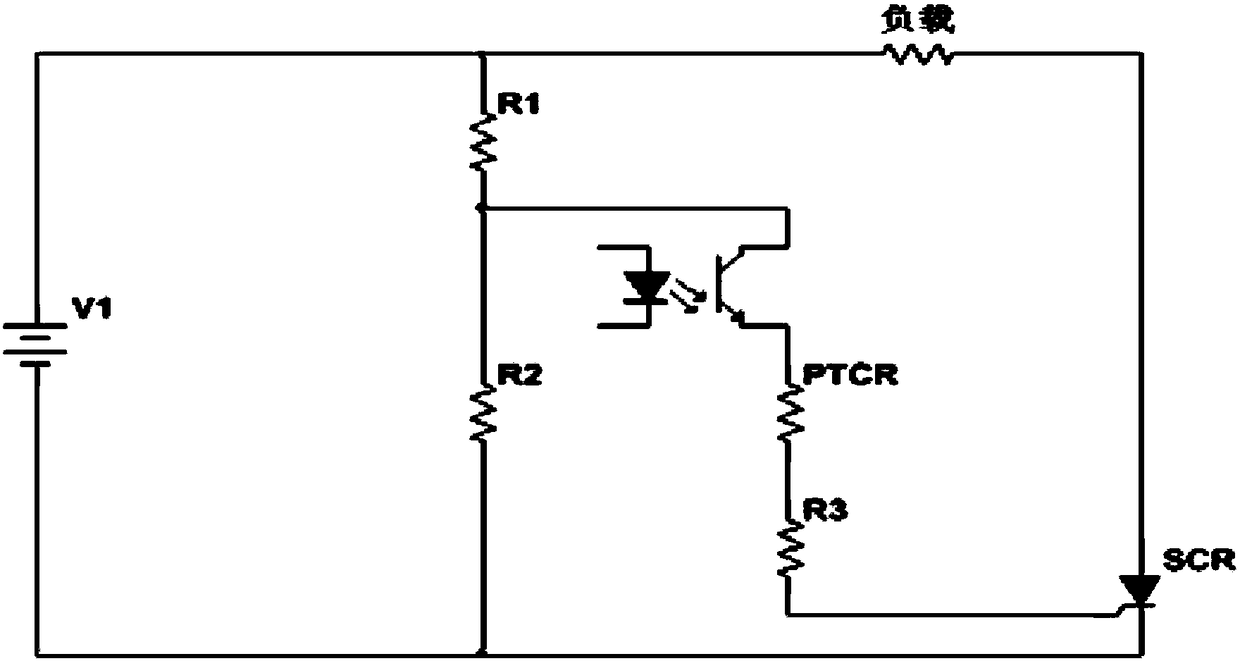
[0016] This embodiment takes the unidirectional thyristor as an example to illustrate the scheme of the thyristor trigger circuit for positive temperature coefficient thermistor compensation of the present invention. In this embodiment, a one-way thyristor is used to control the on-off of the load current in the DC circuit. The control switch in the thyristor trigger circuit is an optocoupler switch with electrical isolation.

[0017] Such as figure 1 As shown, the thyristor trigger circuit based on positive temperature coefficient thermistor compensation includes one-way thyristor SCR, positive temperature coefficient thermistor PTCR, voltage dividing resistor pair R1 and R2, resistor R3, load, optocoupler switch and supply V1. Among them, the voltage dividing resistor pair R1 and R2 are connected in series with the power supply V1; one end of the optocoupler switch is connected to the junction of the voltage dividing resistor pair, and the other end of the optocoupler swit...

Embodiment 2

[0025] In this embodiment, the bidirectional thyristor is taken as an example to illustrate the scheme of the thyristor trigger circuit compensated by the positive temperature coefficient thermistor of the present invention. In this embodiment, bidirectional thyristors are used to control the on-off of the load in the AC power circuit.

[0026] Such as figure 2 As shown, the thyristor trigger circuit based on positive temperature coefficient thermistor compensation includes bidirectional thyristor TRIAC, positive temperature coefficient thermistor PTCR, voltage dividing resistor pair R1 and R2, resistor R3, capacitor C1, load, Optocoupler switch and AC power supply V1. Among them, the voltage dividing resistor pair R1 and R2 are connected in series with the AC power supply V1; one end of the optocoupler switch is connected to the junction of the voltage dividing resistor pair, and the other end of the optocoupler switch is connected to one end of the positive temperature coe...


PUM


Abstract

The invention discloses a silicon-controlled trigger circuit using a positive temperature coefficient thermistor compensation, wherein positive temperature coefficient thermistors for compensating a silicon-controlled trigger current are connected in series in a silicon-controlled trigger loop, the positive temperature coefficient characteristic of the thermistors is used to compensate for the characteristic of the trigger current required to conduct the silicon-controlled with temperature; and the positive temperature coefficient thermistors are connected in series to the control electrode ofthe silicon controlled. The invention solves the problems of high temperature false trigger and low temperature un-triggering of a normal signal caused by the temperature drift generated by the silicon controlled due to temperature change, thereby increasing the use temperature range of the silicon controlled, and expanding the selectable range of the trigger current.

Description

technical field [0001] The invention relates to a thyristor trigger circuit, in particular to a thyristor trigger circuit compensated by a positive temperature coefficient thermistor. Background technique [0002] The semiconductor material that constitutes the thyristor is very sensitive to the change of the surrounding temperature, which causes the parameters of the thyristor to change with the change of temperature, among which the trigger current is affected by the temperature, which is particularly noticeable. When the thyristor works at high temperature, the leakage current increases, and at the same time, the lifetime of the minority carrier in the PN junction increases with the increase of temperature, and the amplification factor increases accordingly. The combination of these two points causes the gate trigger current to decrease rapidly with the increase of temperature. , the trigger current at high temperature is much smaller than that at room temperature, and th...

Claims


Application Information

Patent Timeline
Patent Type & Authority Applications(China)
IPC IPC(8): H03K17/14H03K17/72
CPCH03K17/14H03K17/72H03K2217/0081
Inventor 卢振亚胡杰阮嘉祥陈志武王歆
Owner SOUTH CHINA UNIV OF TECH