Low frequency ripple suppression circuit and control method

A ripple suppression and circuit technology, applied in the control of low-frequency ripple suppression circuits, in the field of low-frequency ripple suppression circuits, can solve the problems of increasing system heat dissipation pressure, increasing system cost and system complexity, and large loss of efficiency

Pending Publication Date: 2018-09-07
SHENZHEN KIWI MICROELECTRONICS CO LTD +1
View PDF0 Cites 7 Cited by
  • Summary
  • Abstract
  • Description
  • Claims
  • Application Information

AI Technical Summary

Problems solved by technology

[0011] Generally, the efficiency of DCDC is about 90% in the industry, so this solution must lose about 10% of the efficiency while increasing the system cost and system complexity, which is not the most ideal choice
[0012] Based on the above, the circuit of Scheme 1 adopts linear drive mode. Although the structure is simple, the efficiency loss is the largest, and the heat dissipation pressure of the system is increased. % or more efficiency, but increases the cost and complexity of the circuit structure

Method used


Image

  • Low frequency ripple suppression circuit and control method
  • Low frequency ripple suppression circuit and control method
  • Low frequency ripple suppression circuit and control method

Examples


Embodiment 1

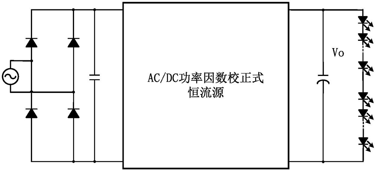
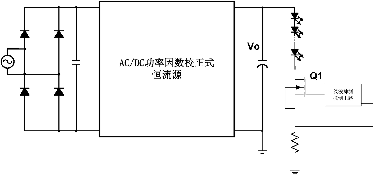
[0100] See Figure 5 , Image 6 The present invention discloses a low-frequency ripple suppression circuit and a control method thereof. The low-frequency ripple suppression circuit includes an energy buffer and a ripple suppression unit, and an AC-DC power factor correction type constant current source circuit. The energy buffer and ripple suppression unit and the LED load are connected in parallel to the constant current source output voltage Vled of the front-stage AC-DC power factor correction constant current source circuit, and the front-stage AC-DC power factor correction constant current source circuit is implemented Power factor correction and constant current output function for the load.

[0101] The AC-DC power factor correction constant current source circuit is a well-known technology in the art, and can be a step-down circuit, a step-up circuit, a flyback circuit, etc. Since it is not the core improvement of the application, it will not be described here.

[0102] Th...

Embodiment 2

[0127] A low-frequency ripple suppression circuit, which includes an energy buffer and a ripple suppression unit, and an AC-DC power factor correction type constant current source circuit;

[0128] The energy buffer and ripple suppression unit and the LED load are connected in parallel to the constant current source output voltage Vled of the front-stage AC-DC power factor correction constant current source circuit, and the front-stage AC-DC power factor correction constant current source circuit is implemented Power factor correction and constant current output function for the load;

[0129] The constant current source output voltage Vled is provided with a second capacitor, and the energy buffer and ripple suppression unit includes a first capacitor Vc1;

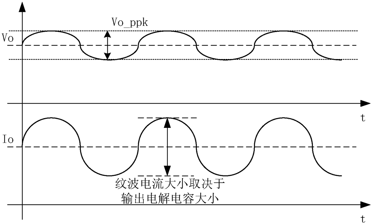
[0130] The energy buffer and ripple suppression unit is used to achieve the effect of low ripple of the previous-stage output voltage Vled; when the current-stage AC-DC power factor correction constant current source circuit out...


PUM


Abstract

The invention discloses a low frequency ripple suppression circuit and a control method. The low frequency ripple suppression circuit comprises an energy buffer and ripple suppression unit and an AC-DC power factor correction type constant current source circuit, wherein the energy buffer and ripple suppression unit is connected in parallel to a constant current source output voltage Vled of the front stage AC-DC power factor correction type constant current source circuit; the AC-DC power factor correction constant current source circuit is used for realizing power factor correction while providing a constant current output for the load; the energy buffer and ripple suppression unit is used for realizing front stage output voltage Vled low ripple; when the output voltage Vled of the frontstage AC-DC power factor correction type constant current source circuit rises instantaneously, energy on a second capacitor is transferred onto a first capacitor to charge the first capacitor; and when the output voltage Vled of the front stage AC-DC power factor correction type constant current source circuit drops instantaneously, the energy on the first capacitor is transferred onto the second capacitor to discharge the first capacitor. Through adoption of the low frequency ripple suppression circuit, LED load ripple can be reduced while ensuring no energy loss and increasing the system efficiency.

Description

Technical field [0001] The invention belongs to the technical field of LED lighting, and relates to an LED constant current drive circuit, in particular to a low-frequency ripple suppression circuit; meanwhile, the invention also relates to a control method of a low-frequency ripple suppression circuit. Background technique [0002] With the rapid development of the lighting industry, LED lamps with extremely high luminous efficiency have fully begun to replace traditional tungsten lamps or energy-saving lamps. With the gradual improvement and improvement of standards and regulations in various countries in the LED lighting industry, the LED market has become more Power factor requirements are getting higher and higher. As the cost pressure gradually increases, single-stage active power factor correction (PFC) LED constant current drive (isolated and non-isolated) has become a mainstream solution to market demand. [0003] However, in the commonly used single-stage active power fa...

Claims


Application Information

Patent Timeline
Patent Type & Authority Applications(China)
IPC IPC(8): H05B33/08H05B44/00
CPCH05B45/00
Inventor 张波王晓佳蔡显彬宋成科
Owner SHENZHEN KIWI MICROELECTRONICS CO LTD
Why Eureka
Try Eureka