Control method and controller

A control method and controller technology, applied in the direction of energy-saving control technology, electrical components, etc., can solve the problems of volume increase, inability to realize LED flicker-free, conduction angle change, etc., achieve dimming function compatibility, and avoid LED flicker problem, no strobe compatible effects

Pending Publication Date: 2022-02-01
SHENZHEN NANYUN MICROELECTRONICS CO LTD
View PDF0 Cites 0 Cited by
  • Summary
  • Abstract
  • Description
  • Claims
  • Application Information

AI Technical Summary

Problems solved by technology

[0004] The existing linear drive thyristor LED dimming power supply circuit such as figure 1 As shown, the scheme has two current limiting units. Current limiting unit 1 is used to set a fixed discharge current to maintain the normal operation of the thyristor. Current limiting unit 2 is used to set a fixed maximum LED current. value, the defect of this scheme is that it cannot realize the requirement of LED without flicker
[0005] figure 2 As an improvement measure under the traditional scheme, it is necessary to add an additional current-limiting unit 3 to help the LED achieve the flicker-free requirement. Since the current-limiting unit 3 is a floating circuit module, an additional single chip is required to implement it, resulting in cost At the same time, the conduction angle of the thyristor dimmer will change under positive and negative voltages, which will still cause flicker
[0006] On this basis, the applicant proposed an adaptive adjustment control scheme to solve the ripple, and its circuit structure is as follows: image 3 As shown, but under this circuit structure, the thyristor dimmer loses the dimming function

Method used


Image

  • Control method and controller
  • Control method and controller
  • Control method and controller

Examples


no. 1 example

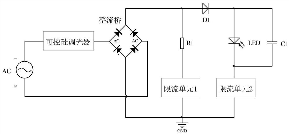
[0093] Figure 5 It is the circuit diagram of the specific implementation of the voltage conversion module in the first embodiment of the present invention, including resistor R2, resistor R3, resistor R4, capacitor C2 and comparator U1; one end of capacitor C2 is input with voltage VB, and the other end of capacitor C2 is connected to resistor R2 at the same time One terminal, one terminal of resistor R3, one terminal of resistor R4 and the positive input terminal of comparator U1, the other terminal of resistor R2 inputs the reference voltage Vref, the other terminal of resistor R3 and the other terminal of resistor R4 are connected to the reference ground GND, the comparator U1 The reference voltage Vref4 is input to the negative input terminal, and the output terminal of the comparator U1 outputs the differential voltage V1.

[0094] Image 6 It is a circuit diagram of a specific implementation of the zero-crossing detection module in the first embodiment of the present i...

no. 2 example

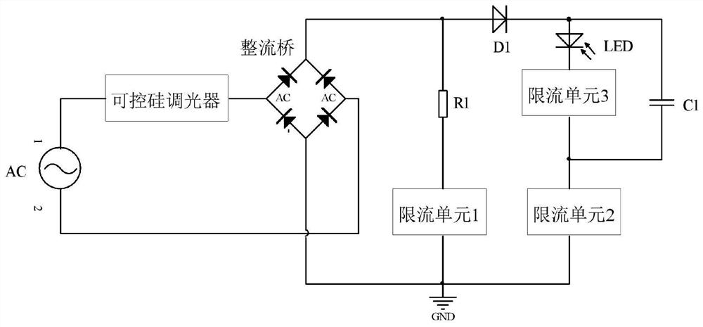
[0109] The voltage conversion module, zero-crossing detection module, and constant current module of this embodiment are the same as those of the first embodiment, and will not be repeated here.

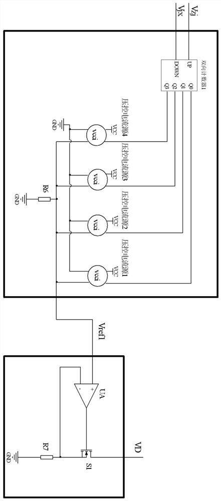
[0110] Figure 9 It is the internal circuit block diagram of the conduction angle detection module in the second embodiment of the present invention, including a counting processing module and a counting 1 module; the counting processing module receives the zero-crossing signal Vz and collects the counting value Count3, and the counting 1 module also receives the zero-crossing signal Vz; In every two adjacent working cycles of the thyristor LED dimming power supply, the signal processing logic of the counting processing module and the counting 1 module is: when the counting processing module receives the zero-crossing signal Vz, it compares the counting value Count3 with the counting threshold 1B compares and processes to obtain the voltage signal Vjx and voltage signal Vzj, and then...


PUM


Abstract

The invention discloses a control method and a controller. The control method is applied to a silicon controlled LED dimming power supply, and in each work cycle of the power supply, the control method comprises the following steps of: a voltage conversion step, specifically, converting a voltage VB representing the magnitude of a bus voltage into a differential voltage V1; a zero-crossing detection step, specifically, detecting the voltage VB, and outputting a zero-crossing signal Vz after detecting that the voltage VB is reduced from high to low; a counting step, specifically, receiving the differential voltage V1, performing resetting when receiving the differential voltage V1, starting counting through a timing reference, and outputting a real-time counting value; a conduction angle detection step, specifically, receiving the zero-crossing signal Vz, and when receiving the zero-crossing signal Vz, collecting a counting value output at the moment in the counting step, and recording the counting value as Count3; an LED current threshold value adjusting step, specifically, generating a reference voltage according to control signals; and a constant current step, specifically, adjusting the magnitude of power supply output driving current according to the reference voltage. According to the control method, in each work cycle of the power supply, the control signals are alternately output according to a first rule or a second rule. According to the control method and the controller of the invention, the stroboflash of an LED can be avoided, and dimming can be realized at the same time.

Description

technical field [0001] The invention relates to the field of LED dimming power supplies, in particular to the control of silicon-controlled LED dimming power supplies. Background technique [0002] Early lighting generally used incandescent lamps, which realized lighting by generating light through resistance wire heating. In order to meet the adjustment of lighting brightness in different applications, a thyristor dimmer was invented. By adjusting the conduction of the thyristor Angle, adjust the effective value of the input voltage to adjust the brightness of incandescent lamps, this kind of dimmer is not only widely used in public places, but also widely used in homes. [0003] With the development of the times, as a new light source, light-emitting diode (LED) is widely used because of its advantages of adjustable color, high luminous efficiency, low power consumption, high reliability and long life. There are many dimming methods for LED light sources, such as thyristo...

Claims


Application Information

Patent Timeline
Patent Type & Authority Applications(China)
IPC IPC(8): H05B45/32
CPCH05B45/32Y02B20/40
Inventor 不公告发明人
Owner SHENZHEN NANYUN MICROELECTRONICS CO LTD
Why Eureka
Try Eureka