Circuit for LED voltage adaptive pwm dimming under constant current source pre-drive

A technology of dimming control circuit and constant current source, applied in the direction of electric lamp circuit arrangement, light source, electric light source, etc., can solve the problem of increasing signal transmission and line connection, increasing the loss of linear current source, affecting the reliability of the front-stage converter, etc. problem, to achieve the effect of low cost and simple control

Active Publication Date: 2015-09-09
ZHEJIANG UNIV
View PDF6 Cites 2 Cited by
  • Summary
  • Abstract
  • Description
  • Claims
  • Application Information

AI Technical Summary

Problems solved by technology

However, since multiple LED loads rely on a common voltage bus to provide energy, when the voltage drop of multiple strings of LEDs has a large difference, for example, the linear constant current source connected in series in the LED string with a smaller voltage drop will bear the same voltage as the LED load. Voltage difference across LED strings with maximum forward voltage drop, resulting in increased linear current source losses
In addition, because the output voltage of the front-end converter needs to be adjusted by detecting the voltage at both ends of the linear current source, the distance between the output signal of the voltage detection circuit and the corresponding linear constant current source is limited, which affects the reliability of the front-end converter regulation. In addition, it also increases the difficulty of signal transmission and line connection, and limits the independence and standardization of the pre-driver

Method used


Image

  • Circuit for LED voltage adaptive pwm dimming under constant current source pre-drive
  • Circuit for LED voltage adaptive pwm dimming under constant current source pre-drive
  • Circuit for LED voltage adaptive pwm dimming under constant current source pre-drive

Examples


Embodiment Construction

[0023] Embodiments of the present invention will be described in detail below in conjunction with the accompanying drawings.

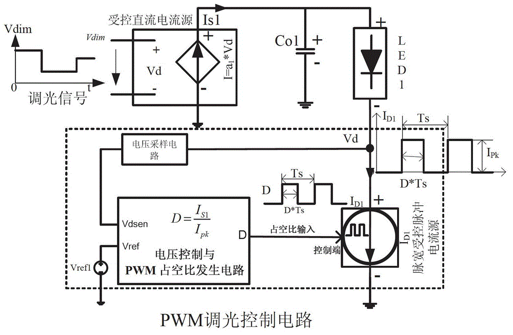
[0024] Such as figure 2 As shown, the present invention includes a pre-stage controlled DC current source Is1, an output filter capacitor Co1, and an output load LED string LED1. The latter stage is a PWM dimming control circuit with constant pulse width and constant pulse width controlled by terminal voltage adaptive control, including pulse current source ID1, voltage sampling circuit for collecting pulse current source terminal voltage, voltage control and PWM duty cycle generation circuit. The controlled DC current source Is1 is controlled by the dimming signal Vdim. The output filter capacitor Co1 is connected in parallel to both ends of the controlled DC current source Is1, and the output load LED string LED1 is connected in series with the PWM dimming control circuit and then connected in parallel to both ends of the controlled DC current sou...


PUM


Abstract

The invention relates to a PWM (Pulse Width Modulation) light adjusting technology for an LED (Light Emitting Diode) and aims at providing a circuit for realizing the voltage-self-adaptation PWM light adjustment of the LED under the drive of a prepositive constant-current source. The circuit comprises an output load LED string LED1, an output filter capacitor Co1, a forestage controlled direct-current (DC) source Is1 and a PWM light adjusting control circuit which is connected with the LED string LED1, wherein the filter capacitor Co1 is in parallel connection with the two terminals of the controlled DC source Is1, the LED string LED1 is in series connection with the PWM light adjusting control circuit and then in parallel connection with the two terminals of the Is1, and a light adjusting signal input terminal is connected to the control terminal of the controlled DC source Is1. According to the circuit for realizing the voltage-self-adaptation PWM light adjustment of the LED under the drive of the prepositive constant-current source, the forestage constant-current source and the rear-stage PWM control circuit are out of additional signal circuit connection, besides being in power connection, so that the control is simple; the average terminal of the rear-stage PWM pulse constant current source obtains the minimum voltage through self adaptation, so that the conduction losses are reduced; the PWM light adjustment of the LED can be realized without PWM light adjusting signals; the M light adjusting function is realized in an analog mode, so that the cost is low; and the multichannel PWM light adjusting control can be realized by adopting a multichannel output constant current source, and only light adjusting signals of one channel are used.

Description

technical field [0001] The invention relates to a realization method of pulse width (PWM) dimming of LEDs, in particular to a control method for realizing PWM dimming of LEDs driven by a constant current source. Background technique [0002] High-power LEDs have become a new generation of green light sources due to their long life, high luminous efficiency, and environmental friendliness. LEDs are not only used in traditional lighting occasions to replace ordinary existing light sources, but also more widely used in occasions that require high dimming, such as LCD backlighting. Since the color temperature of the LED will change with the amplitude of the driving current, in order to ensure the consistency of the color temperature, it is required to maintain the amplitude of the current during dimming, and to perform dimming by changing the conduction time of the current, that is, the commonly used PWM dimming method. Due to the diode characteristics of the LED, it needs to ...

Claims


Application Information

Patent Timeline
Patent Type & Authority Patents(China)
IPC IPC(8): H05B37/02
Inventor 吴新科
Owner ZHEJIANG UNIV
Why Eureka
Try Eureka