High power factor low harmonic distortion constant current circuit and device

A high power factor, constant current circuit technology, applied in the direction of output power conversion device, DC power input conversion to DC power output, electrical components, etc., can solve the problems of large ripple current, unsuitable, stroboscopic, etc.

Active Publication Date: 2016-08-17
HANGZHOU SILAN MICROELECTRONICS
View PDF4 Cites 0 Cited by
  • Summary
  • Abstract
  • Description
  • Claims
  • Application Information

AI Technical Summary

Problems solved by technology

[0006] by figure 2 Taking the single-stage step-down PFC circuit as an example, although the circuit structure is simple and the circuit cost is low, the disadvantage is that there is a large ripple current (usually 100Hz ripple current) in the output load, which will cause flicker and cannot be applied to Some applications that require high strobe

Method used


Image

  • High power factor low harmonic distortion constant current circuit and device
  • High power factor low harmonic distortion constant current circuit and device
  • High power factor low harmonic distortion constant current circuit and device

Examples


no. 1 example

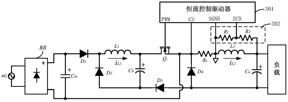
[0120] refer to image 3 , image 3 It shows the high power factor low harmonic distortion constant current device of the first embodiment, including a high power factor low harmonic distortion constant current circuit and a constant current control driver 301 connected thereto. Among them, the high power factor low harmonic distortion constant current circuit includes a rectifier bridge BR, a pre-stage circuit and a post-stage circuit. The pre-stage circuit is a buck-boost circuit, and the post-stage circuit is a step-down circuit. The same switch Q 1 and bus capacitance C b .

[0121] More specifically, the pre-stage circuit in the first embodiment includes: an input capacitor C in , the first diode D 1 , the first inductance L 1 , Bus capacitance C b , the second diode D 2 , switch tube Q 1 ; The post-stage circuit includes: bus capacitor C b , switch tube Q 1 , the third diode D 3 , Sampling resistor R s , the second inductance L 2 , the fourth diode D 4 and...

no. 2 example

[0133] refer to Figure 7 , Figure 7 Shown is the high power factor low harmonic distortion constant current device of the second embodiment. The high power factor low harmonic distortion constant current circuit of this embodiment is basically the same as the aforementioned first embodiment, and the working principle is also basically the same, so it will not be described in detail.

[0134] The high power factor low harmonic distortion constant current circuit of this embodiment and image 3 The first embodiment shown is different in that the junction of the constant current control driver 701 and the high power factor low harmonic distortion constant current circuit is changed. In this embodiment, the ground terminal SGND of the constant current control driver 701 is connected to the sampling resistor R s The first terminal of the constant current control driver 701, the current sampling terminal CS is connected to the sampling resistor R s Therefore, the current infor...

no. 3 example

[0136] refer to Figure 8 , Figure 8 Shown is the high power factor low harmonic distortion constant current device of the third embodiment. This embodiment and image 3 The first embodiment shown differs in that the second inductance L 2 The current zero-crossing detection method is different.

[0137] In this embodiment, it also includes the second inductance L 2 Coupled auxiliary winding L 2a , auxiliary winding L 2a used to detect the second inductance L 2 The current zero-crossing information, the second inductance L 2 equivalent and auxiliary winding L 2a coupled to form a transformer, the auxiliary winding L 2a The opposite end of the ground, the auxiliary winding L 2a The terminal with the same name as the resistor divider network 302 is connected to the input terminal. Wherein, the resistor divider network 302 includes resistors R connected in series 1 and resistor R 2 .

[0138] The main circuit of this embodiment and image 3 The first embodiment sho...


PUM


Abstract

The invention provides a high-power-factor low-harmonic-distortion constant current circuit and device. The circuit comprises a front-level circuit and a rear-level circuit which are coupled mutually, wherein the front-level circuit is a boost-buck circuit used for correcting a power factor, the rear-level circuit is a buck circuit used for direct current-direct current conversion, and moreover the front-level circuit and the rear-level circuit share the same switching tube and the same bus capacitor. Compared with a two-level structure, the devices are fewer, and cost is lower; compared with a single-level buck structure, the output load current ripple is smaller, and the constant current circuit is higher in power factor and lower in total harmonic distortion.

Description

technical field [0001] The invention relates to switching power supply technology, in particular to a constant current circuit and device with high power factor and low harmonic distortion. Background technique [0002] At present, due to the presence of nonlinear components and energy storage components in most electrical equipment, the input AC current waveform will be severely distorted, and the input power factor of the grid side is very low. In order to meet the harmonic requirements of the international standard IEC61000-3-2, Power factor correction (PFC) devices must be added to these electrical appliances. [0003] In order to solve the problem of low power factor, single-stage or two-stage power factor correction (PFC) circuit technology has been widely used in AC-DC power converters. [0004] Compared with the single-stage power factor correction technology, the two-stage power factor correction technology has the characteristics of small output ripple and high po...

Claims


Application Information

Patent Timeline
Patent Type & Authority Patents(China)
IPC IPC(8): H02M3/155H02M1/14
Inventor 蔡拥军叶美盼汪丞辉谢小高
Owner HANGZHOU SILAN MICROELECTRONICS
Why Eureka
Try Eureka