Stroboflash-free eye protection table lamp control system
A control system and flicker-free technology, which is applied in the field of flicker-free systems, can solve the problems of not necessarily accurate, accurate judgment of stroboscopic depth, more severe stroboscopic, etc., and achieve the effect of solving desk lamp stroboscopic and easy adjustment
- Summary
- Abstract
- Description
- Claims
- Application Information
AI Technical Summary
Problems solved by technology
Method used
Image
Examples
Embodiment 1
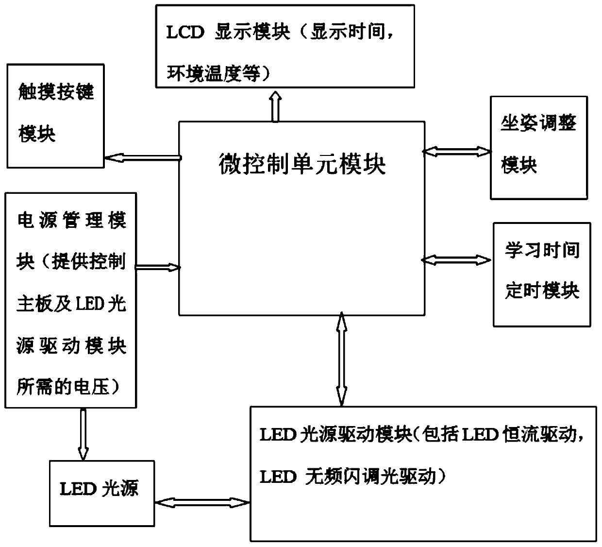
[0028] Embodiment 1: A kind of flicker-free eye protection table lamp control system, such as figure 1 As shown, it includes the micro control unit module, the micro control unit module is electrically connected with the LCD display module, the touch key module, the power management module, the LED light source driver module, the learning time timing module, the sitting posture adjustment module, and the power management module is one-way electrical The LED light source is connected to the LED light source, and the LED light source is electrically connected to the LED light source drive module in two directions. The output end of the micro control unit module is electrically connected to the input end of the LCD display module and the touch button module, and the micro control unit module is connected to the sitting posture adjustment module and learning time. The timing module and the LED light source drive module are electrically connected in two directions, the output end of t...
Embodiment 2
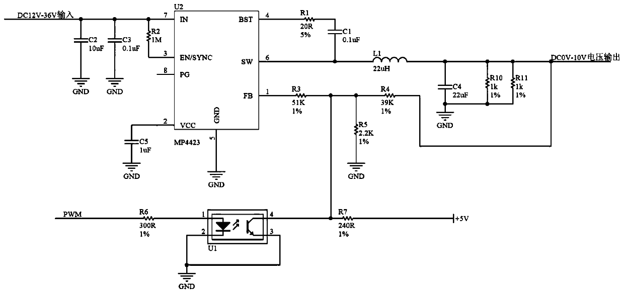
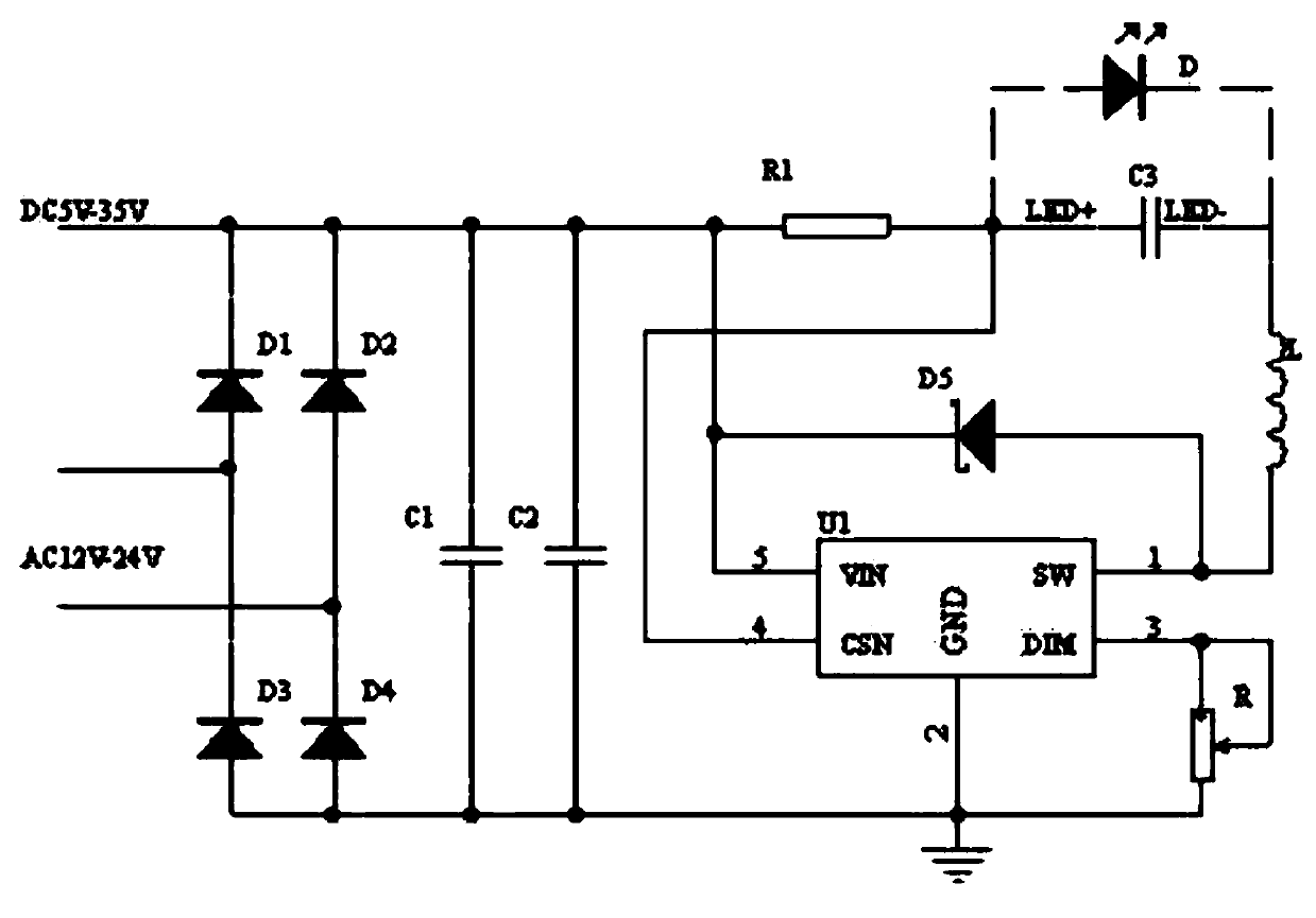
[0029] Embodiment 2: A kind of flicker-free eye protection desk lamp control system, such as figure 2 , 3 As shown, the LED light source driver module includes LED driver chip U1, step-down chip U2, pulse width modulation signal PWM, LED light source adjustment D, and power input module. The power input module is connected to the step-down chip U2, and one end of the step-down chip U2 is connected to a Pulse width modulation signal PWM, the other end of the step-down chip U2 is connected to a 0-10V voltage output and connected to the LED driver chip U1, the LED driver chip U1 is connected to the LED light source regulator D, the output of the power input module is connected to the input of the step-down chip U2 The terminals are electrically connected, the output terminal of the FB port of the step-down chip U2 is electrically connected to the input terminal of the pulse width modulation signal PWM, and the output terminals of the BST, SW, and FB ports of the step-down chip U...
Embodiment 3
[0030] Embodiment 3: A kind of flicker-free eye protection desk lamp control system, such as Figure 4 As shown, another structure of LED light source driver module includes digital potentiometer AD5231, 15V voltage input, 5V voltage input, signal amplifier A1, 0-10V voltage output, LED driver chip U1, LED light source adjustment D, 5V voltage input connection There is digital potentiometer AD5231, 15V voltage input is connected to signal amplifier A1, digital potentiometer AD5231 is connected to signal amplifier A1, signal amplifier A1 is connected to LED driver chip U1, LED driver chip U1 is connected to LED light source adjustment D, 5V voltage input The output terminal is electrically connected to the input terminal of the digital potentiometer AD5231, the output terminal of the 15V voltage input is electrically connected to the input terminal of the signal amplifier A1, the output terminal of the digital potentiometer AD5231 is electrically connected to the input terminal ...
PUM
 Abstract
Description
Claims
Application Information
 - R&D
- Intellectual Property
- Life Sciences
- Materials
- Tech Scout
- Unparalleled Data Quality
- Higher Quality Content
- 60% Fewer Hallucinations
Browse by: Latest US Patents, China's latest patents, Technical Efficacy Thesaurus, Application Domain, Technology Topic, Popular Technical Reports.
© 2025 PatSnap. All rights reserved.Legal|Privacy policy|Modern Slavery Act Transparency Statement|Sitemap|About US| Contact US: help@patsnap.com


