Check patentability & draft patents in minutes with Patsnap Eureka AI!

Hydraulic height-adjustable turning tool

A hydraulic and high-level technology, applied in the direction of tools for lathes, turning equipment, accessories of tool holders, etc., can solve the problems of cutting tools, lower actual center height of installed tools, poor flatness of gaskets, etc., to achieve practical Strong and easy to operate

Active Publication Date: 2018-09-11
重庆西迪齿轮有限公司
View PDF8 Cites 0 Cited by
  • Summary
  • Abstract
  • Description
  • Claims
  • Application Information

AI Technical Summary

Problems solved by technology

[0002] Lathes, including ordinary lathes and CNC lathes, require that the tip of the tool must be at the center height of the rotating part during processing, otherwise the actual rake angle and rear angle of the cutting tool will be changed, or the part cannot be cut during cutting, and it is very easy to cause For cutting tools, the center height of the tool is fixed after the traditional tool is manufactured. For welded turning tools, after the tool is sharpened, especially after the rake face is sharpened, the actual center height of the installed tool will become lower. The traditional method is to use some gaskets with different thicknesses for installation and adjustment. This method is time-consuming and laborious to adjust the center height, and because the flatness of the gaskets after repeated use is not good, especially after the combination of multiple pieces, due to the The flatness of the sheet is not good, and it will cause the phenomenon of unreliable installation when the screw is tightened

Method used


Image

  • Hydraulic height-adjustable turning tool
  • Hydraulic height-adjustable turning tool
  • Hydraulic height-adjustable turning tool

Examples


Embodiment

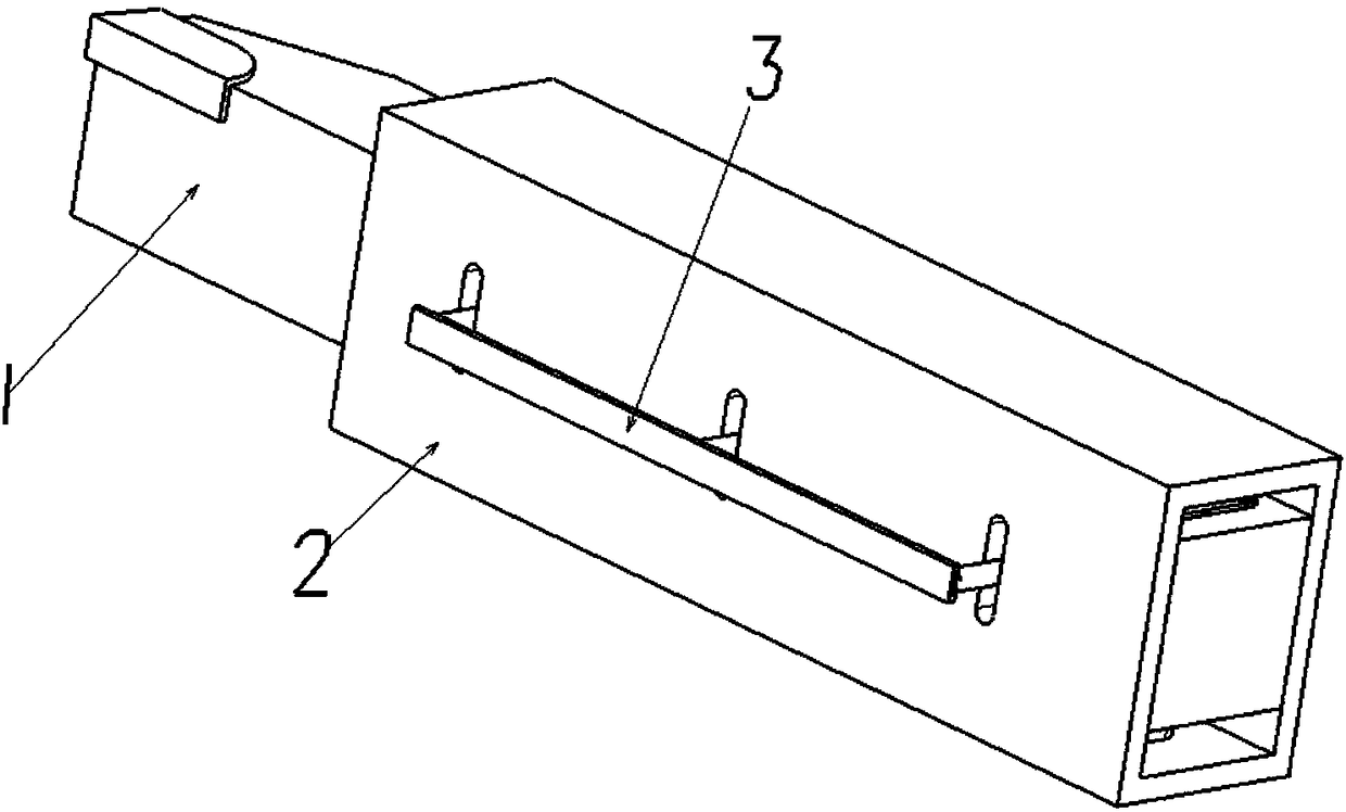
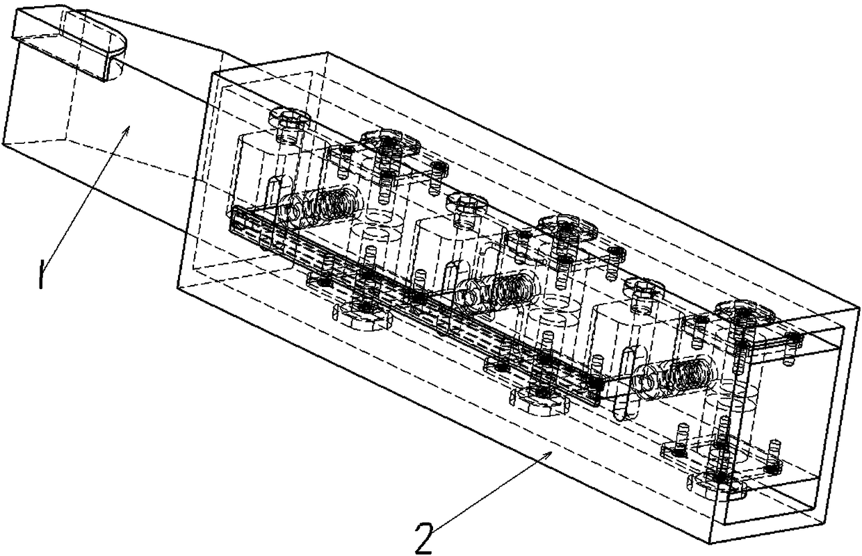
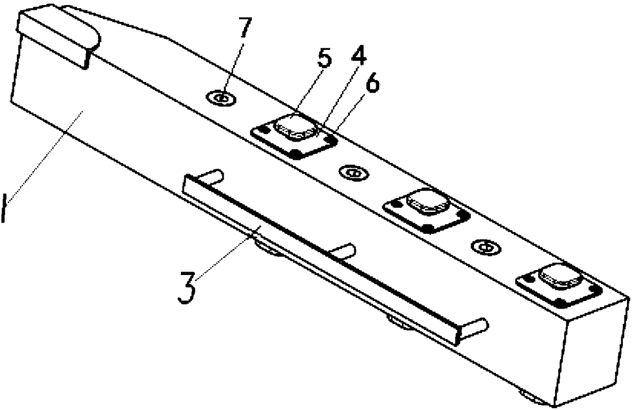
[0042] The hydraulic height-adjustable turning tool proposed by the present invention can use 3 sets of hydraulic height-adjusting mechanisms. When installed on a lathe, the installation position should ensure that the end of the piston 5 is aligned with the tightening screw on the tool holder, and then push the handle 3 , after the pull-out valve 8 is moved, the oil circuit is connected, and then the height of the cutter body 1 is adjusted to a suitable position, and the handle 3 is released, and the pull-out valve 8 returns to its position under the action of the spring 9, while pulling The piston of type valve 8 blocks the oil passage, and the piston 5 inside the cutter body 1 cannot move, and the height of the cutter body 1 is fixed and locked.

[0043] The hydraulically height-adjustable turning tool of the present invention has the following advantages: it can be conveniently used in lathe processing, and the installation height of the turning tool can be adjusted steples...


PUM


Abstract

The invention discloses a hydraulic height-adjustable turning tool which comprises a tool body. The tool body is provided with a plurality of sets of hydraulic height adjusting mechanisms, each hydraulic height adjusting mechanism comprises a first oil cylinder which is a cylinder hole located between the two opposite upper and lower bottom faces of the tool body in the axial direction, a piston is arranged in each first oil cylinder, the end of each piston penetrates an end cover, a rubber ring is further arranged between each end cover and a groove, one side of each first oil cylinder is sequentially provided with a second oil cylinder and a hydraulic oil storage cavity, a push-and-pull type valve is arranged in each second oil cylinder, a first oil pipe communicating with the front endof the top of each second oil cylinder is arranged at the upper portion of the corresponding first oil cylinder, a third oil pipe and a fourth oil pipe are arranged at the bottom of each second oil cylinder and communicate with the corresponding hydraulic oil storage cavity, a supporting frame is arranged outside the tool body in a sleeving manner, rectangle through grooves are formed in the sidewall of the supporting frame, the ends of the push-and-pull type valves penetrate the rectangle through grooves, and handles are installed at the ends of the push-and-pull type valves. By means of thehydraulic height-adjustable turning tool, the center height of the turning tool can be quickly adjusted.

Description

technical field [0001] The invention belongs to the technical field of turning tools, and in particular relates to a hydraulically height-adjustable turning tool. Background technique [0002] Lathes, including ordinary lathes and CNC lathes, require that the tip of the tool must be at the center height of the rotating part during processing, otherwise the actual rake angle and rear angle of the cutting tool will be changed, or the part cannot be cut during cutting, and it is very easy to cause For cutting tools, the center height of the tool is fixed after the traditional tool is manufactured. For welded turning tools, after the tool is sharpened, especially after the rake face is sharpened, the actual center height of the installed tool will become lower. The traditional method is to use some gaskets with different thicknesses for installation and adjustment. This method is time-consuming and laborious to adjust the center height, and because the flatness of the gaskets af...

Claims


Application Information

Patent Timeline
IPC IPC(8): B23B27/00B23B29/06
CPCB23B27/00B23B29/06
Inventor 庞勇刘磐吴立明
Owner 重庆西迪齿轮有限公司
Features
  • R&D
  • Intellectual Property
  • Life Sciences
  • Materials
  • Tech Scout
  • Unparalleled Data Quality
  • Higher Quality Content
  • 60% Fewer Hallucinations
Learn More