Adaptive Robot Finger Device for Slide Bar Delayed Displacement Linear Flat Clamp
What is Al technical title?
Al technical title is built by PatSnap Al team. It summarizes the technical point description of the patent document.
A robot finger, self-adaptive technology, applied in the directions of manipulators, chucks, manufacturing tools, etc., can solve the problem of unable to achieve self-adaptive envelope grasping, unable to achieve linear translation of the end finger segment, and increase the collaborative control programming of the manipulator arm. dependencies, etc.
Active Publication Date: 2020-09-25
TSINGHUA UNIV
View PDF1 Cites 0 Cited by
Summary
Abstract
Description
Claims
Application Information
AI Technical Summary
This helps you quickly interpret patents by identifying the three key elements:
Problems solved by technology
Method used
Benefits of technology
Problems solved by technology
Its shortcoming is that the device can only realize the linear parallel clamping function, and cannot realize the function of adaptive envelope grabbing
The disadvantage of this device is that in the stage of grasping by the flat clip, the end of the finger moves in a circular arc——the end of the circular arc moves in translation, which cannot achieve the effect of linear translation of the end finger segment. , requires the precise linear translational control cooperation of the manipulator, thus increasing the dependence on the cooperative control programming of the manipulator
Method used
Image
Click on the blue label to locate the original text in one second.
Reading with bidirectional positioning of images and text.
Examples
Embodiment Construction
[0037] The specific structure and working principle of the present invention will be further described in detail below in conjunction with the accompanying drawings and embodiments.
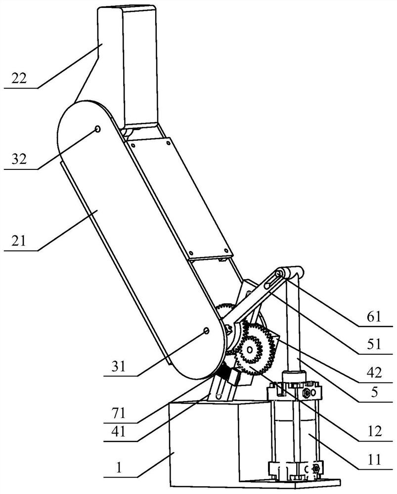
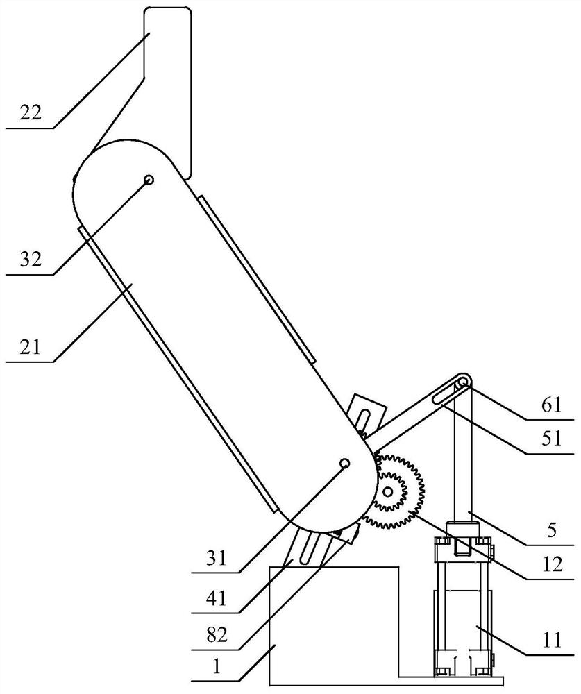
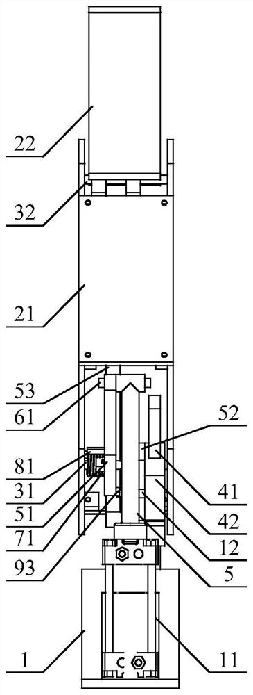
[0038] An embodiment of the sliding bar time-delay displacement linear flat clip self-adaptive robot finger device designed by the present invention, such as Figure 1 to Figure 6 As shown, it includes a base 1, a first finger segment 21, a second finger segment 22, a proximal joint shaft 31, a distal joint shaft 32 and a motor 11; the motor 11 is fixedly connected to the base 1; the first finger segment 21 is sleeved on the proximal joint shaft 31; the distal joint shaft 32 is sleeved in the first finger segment 21; the second finger segment 22 is sleeved on the distal joint shaft 32; the center of the proximal joint shaft 31 line and the central line of the distal joint shaft 32 are parallel to each other; it is characterized in that: the sliding bar time-delay displacement linear flat clip ada...
PUM
Abstract
The invention discloses a sliding rod delay deflection linear parallel-clamping adaptive robot finger device and belongs to the technical field of robot hands. The sliding rod delay deflection linearparallel-clamping adaptive robot finger device comprises a base, a motor, a drive mechanism, a sliding chute piece, a sliding block, a sliding rod, a first finger section, a second finger section, a near articulated shaft, a far articulated shaft, a first shaft, a second shaft, a third shaft, a first connection rod, a second connection rod, a third connection rod, a first spring, a second spring,a lug, a driven lug, a first limiting block, a second limiting block and a drive stirring block. By means of the device, the robot finger linear parallel-clamping clamping and adaptive grabbing functions are achieved; the device can linearly move the second finger section in parallel to pinch an object, thereby being suitable for a workbench to grab sheet-like objects, the first finger section canbe rotated at first, and then the second finger section is subjected to delay deflection rotation to wrap the objects in different shapes and sizes; the device is large in grabbing range; the two finger sections are driven through one motor, and no complicated sensing and control system is needed; and the device is compact in structure, small in size, low in manufacturing and maintenance cost andsuitable for robot hands.
Description
technical field [0001] The invention belongs to the technical field of robot hands, and in particular relates to a structural design of a sliding bar time-delay displacement linear flat clip self-adaptive robot finger device. Background technique [0002] The robot hand is an important device for the robot system to realize the grasping function. The method of grabbing an object is to limit the possibility of movement of the object in that direction from two opposite directions. There are multiple directions for the movement of objects in space. In order to limit the various movement possibilities of the grasped objects, the robot hand needs to display different grasping modes for different grasping objects, thereby limiting the movement of objects in all directions. Parallel clamping grasping (referred to as flat clamping grasping) is a common grasping method. The terminal finger segments always maintain a relatively fixed posture relative to the palm base during the movem...
Claims
Application Information
Patent Timeline
Application Date:The date an application was filed.
Publication Date:The date a patent or application was officially published.
First Publication Date:The earliest publication date of a patent with the same application number.
Issue Date:Publication date of the patent grant document.
PCT Entry Date:The Entry date of PCT National Phase.
Estimated Expiry Date:The statutory expiry date of a patent right according to the Patent Law, and it is the longest term of protection that the patent right can achieve without the termination of the patent right due to other reasons(Term extension factor has been taken into account ).
Invalid Date:Actual expiry date is based on effective date or publication date of legal transaction data of invalid patent.