A valve mechanism and engine capable of monitoring valve clearance on-line

A valve clearance and valve mechanism technology, which is applied in the directions of machines/engines, engine components, mechanical equipment, etc., can solve the problems of accurately monitoring the actual valve clearance, etc., and achieve the effects of accurate and reliable monitoring results and simple monitoring structure.

Active Publication Date: 2020-08-21
WEICHAI POWER CO LTD
View PDF10 Cites 0 Cited by
  • Summary
  • Abstract
  • Description
  • Claims
  • Application Information

AI Technical Summary

Problems solved by technology

[0006] One object of the present invention is to provide a valve mechanism and an engine capable of monitoring the valve clearance online, so as to solve the problem in the prior art that it is impossible to accurately monitor whether the actual clearance of the valve meets the requirements when the vehicle is running.

Method used


Image

  • A valve mechanism and engine capable of monitoring valve clearance on-line
  • A valve mechanism and engine capable of monitoring valve clearance on-line
  • A valve mechanism and engine capable of monitoring valve clearance on-line

Examples


Embodiment Construction

[0039] The technical solutions of the present invention will be further described below in conjunction with the drawings and specific implementations.

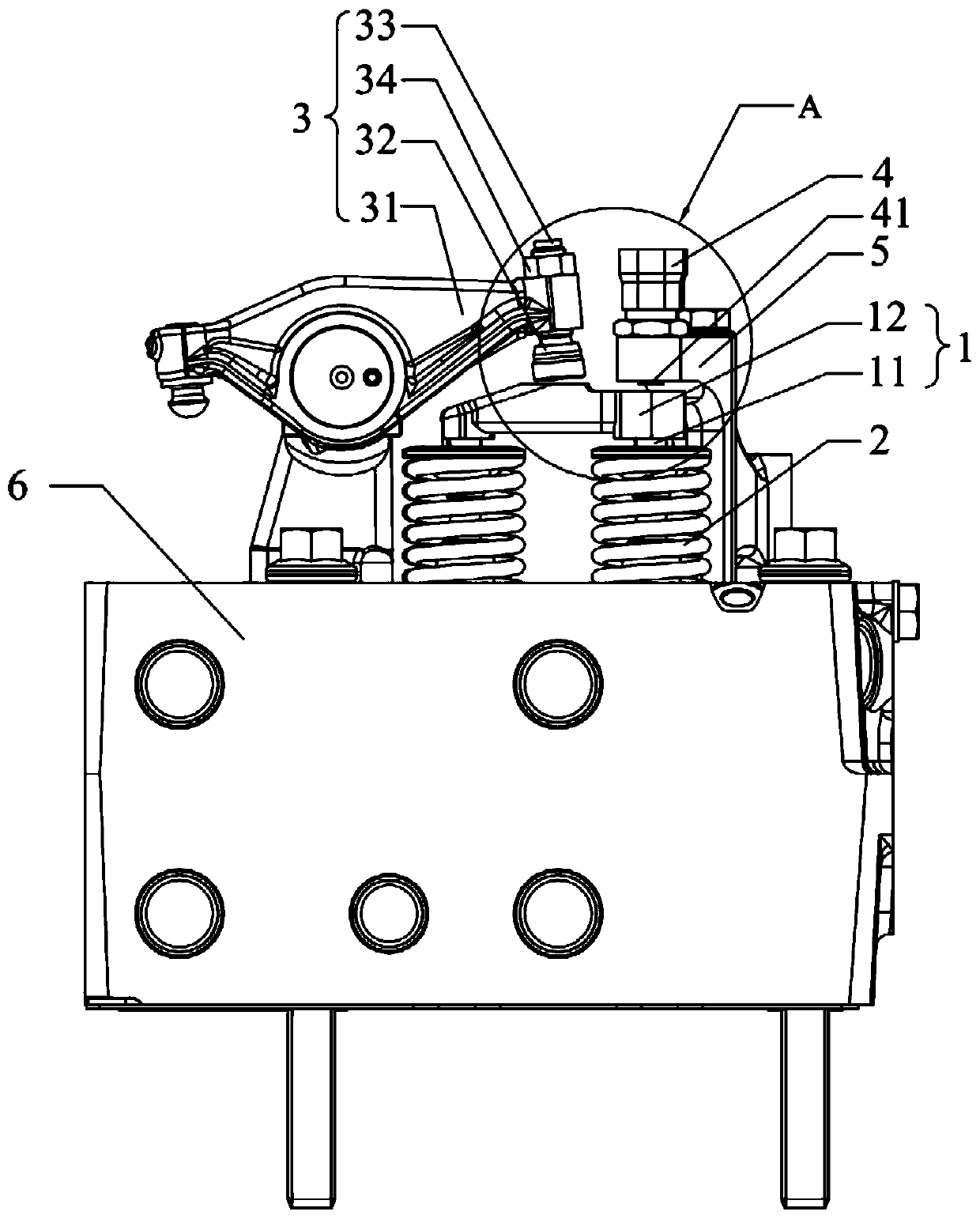
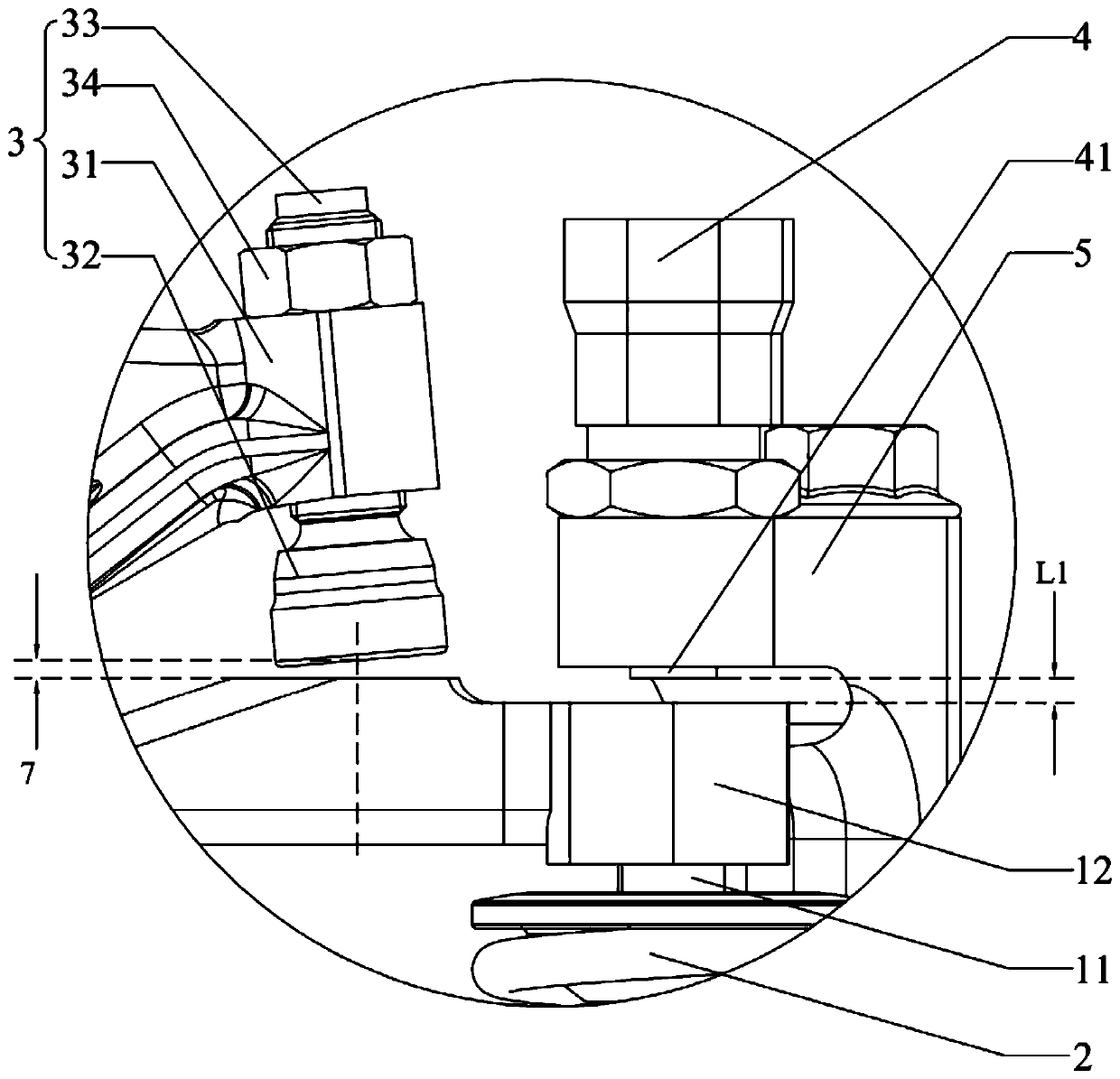
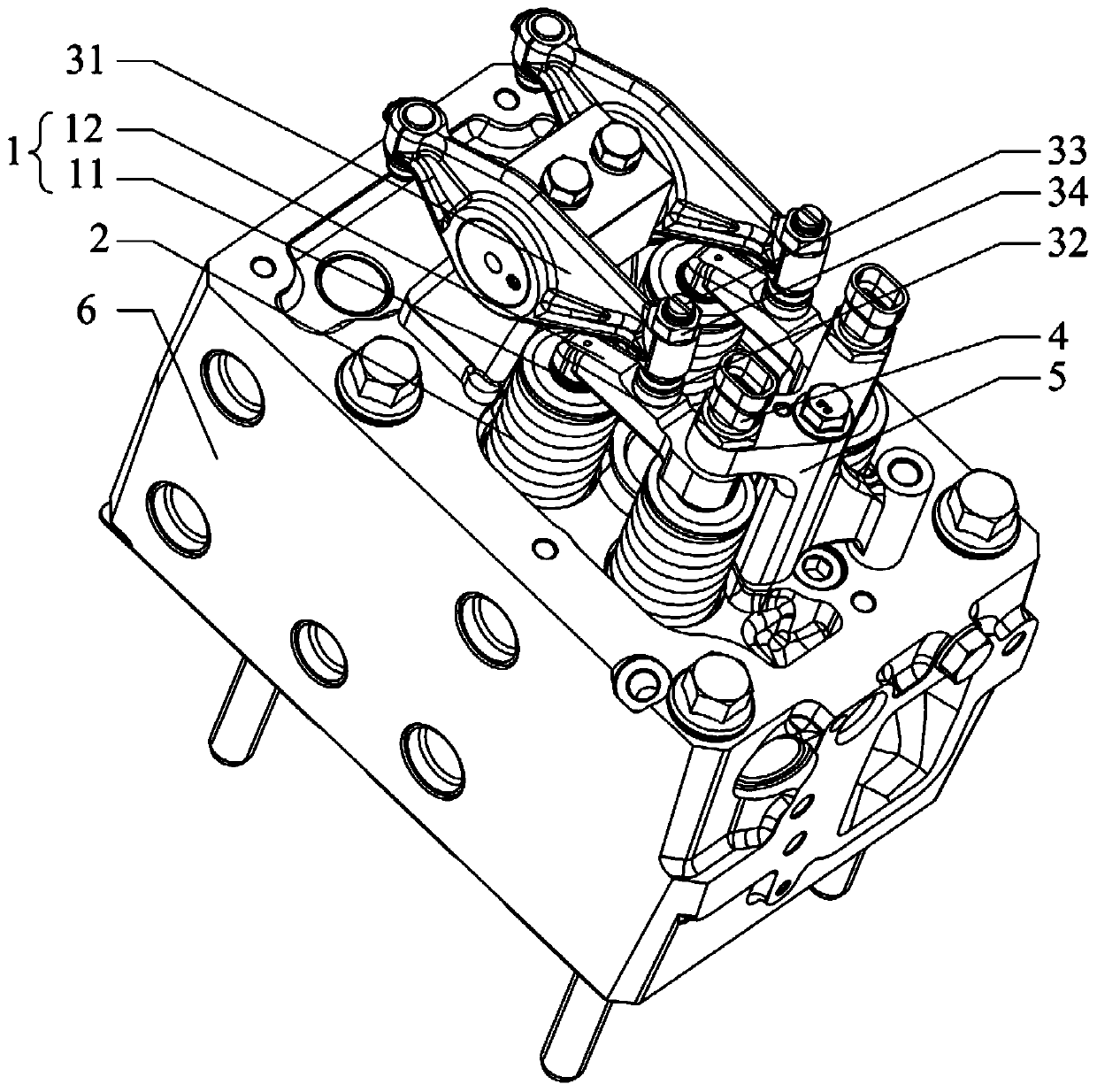
[0040] This embodiment provides a valve mechanism that can monitor valve clearance online, such as Figure 1~3 As shown, it includes: a valve assembly 1, a rocker arm assembly 3, a valve spring 2, a valve seat (not shown in the drawings), a valve wear sensor 4, and a sensor bracket 5. The valve assembly 1 is used for engine exhaust or intake, and it passes through the cylinder head 6 of the engine, the valve spring 2 passes through the valve assembly 1, and the top end of the valve spring 2 and the valve assembly 1 near the top of the boss When abutting, one end of the bottom abuts against the cylinder head 6 and the valve spring 2 is in a compressed state, which applies a force away from the cylinder head 6 to the top of the valve assembly 1 to facilitate the return of the valve assembly 1 after the rocker arm assembly 3 is pres...


PUM


Abstract

The invention relates to the field of engines, and specifically discloses a valve mechanism capable of monitoring valve clearance on line and an engine. The valve mechanism comprises a valve assembly,valve springs, a valve seat ring, a rocker arm assembly and a valve abrasion loss sensor. The valve assembly is arranged on a cylinder cover of the engine in a penetrating manner. The valve springs are arranged on the valve assembly in a penetrating manner. The two ends of each valve spring elastically abut against the valve assembly and the cylinder cover correspondingly. The valve seat spring is arranged on the valve assembly in a penetrating manner and located between the valve assembly and the cylinder cover. One end of the rocker arm assembly is connected with an ejection rod, the otherend of the rocker arm assembly is connected with the valve assembly in the thermal state of the engine, the middle portion of the rocker arm assembly is hinged to the cylinder cover, and the preset valve clearance is set for the rocker arm assembly and the valve assembly in the cold state of the engine. The valve abrasion loss sensor is located above the valve assembly. In the cold state of the engine, the distance between the valve abrasion loss sensor and the valve assembly is equal to the sum of the preset valve clearance value and the preset valve seat ring abrasion loss. According to thevalve mechanism and the engine, the abrasion situation of the valve seat ring is monitored by monitoring changes of the actual valve clearance in real time through the valve abrasion loss sensor, andthe monitoring result is accurate and reliable.

Description

Technical field [0001] The invention relates to the field of engine manufacturing, in particular to a valve mechanism and an engine capable of online monitoring of valve clearance. Background technique [0002] When the engine is running, the valve movement can be divided into two strokes: valve opening and valve closing. During the valve opening stroke, the valve moves downward under the action of the rocker arm until the valve is fully opened, and then enters the valve closing stroke, the valve is acted on by the spring force Move up until the valve is seated, and so on. [0003] When the engine is working, the valve will expand due to the increase in temperature. If there is no gap between the valve and its transmission parts in the cold state or the gap is too small, in the hot state, the thermal expansion of the valve and its transmission parts will inevitably cause the valve to close tightly, causing the engine to leak during the compression stroke and the power stroke. As ...

Claims


Application Information

Patent Timeline
Patent Type & Authority Patents(China)
IPC IPC(8): F01L31/08F01L1/22F01L1/46
CPCF01L1/22F01L1/46F01L31/08
Inventor 王贵琛王文慧
Owner WEICHAI POWER CO LTD
Why Eureka
Try Eureka