Bearing mechanism for locomotive weighing platform, measuring mechanism unit, and weighing platform
A bearing mechanism, vehicle weighing technology, applied in the detailed information of weighing equipment, weighing, measuring devices, etc., can solve the problems of complex installation and maintenance, complex structure, poor stability, etc., to achieve compact size, small size, and stability. good effect
- Summary
- Abstract
- Description
- Claims
- Application Information
AI Technical Summary
Benefits of technology
Problems solved by technology
Method used
Image
Examples
Embodiment 1
[0029] Embodiment 1: An end load-carrying mechanism of a load-carrying mechanism for a locomotive and vehicle weighing platform
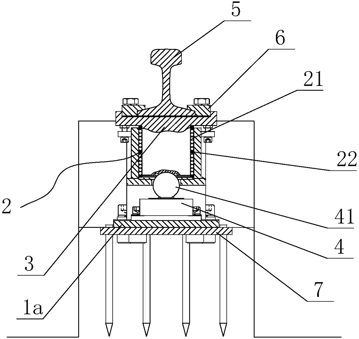
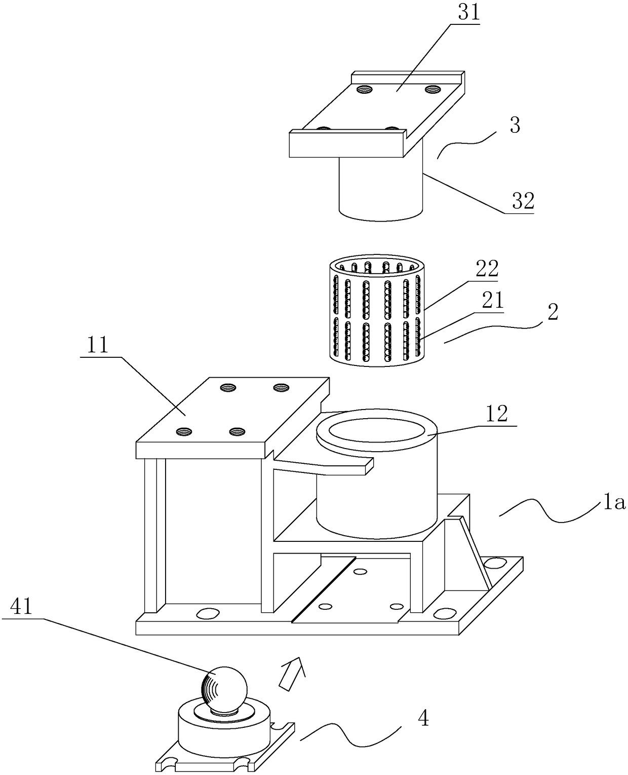
[0030] A bearing mechanism for a rolling stock weighing platform, such as figure 1 As shown, the carrying mechanism includes a base I1a, a linear rolling bearing cage 2, a bearing column 3, and a spoke pressure sensor 4; the base I1a is divided into two parts: a part of which is used as a mechanism 11 for installing a transition rail; the other One part is divided into upper and lower parts, the upper part is used as the housing 12 of the linear rolling shaft, and the lower part is used as the mounting seat of the spoke pressure sensor. The upper part of the bearing column 3 is a square body, and the square body is provided with a groove 31 for placing the weighing rail, and a linear rolling bearing guide sleeve auxiliary guide rail shaft 32 (cylindrical) is arranged below the square body; The linear rolling bearing cage 2 is socketed with the line...
Embodiment 2
[0034]Embodiment 2: A middle load-carrying mechanism of a load-bearing mechanism for a locomotive and vehicle weighing platform
[0035] The specific structure of the middle part bearing mechanism of the present embodiment 2 is as follows: Figure 4 As shown, the middle bearing mechanism includes a base II1b, a linear rolling bearing cage 2, a bearing column 3, and a spoke pressure sensor 4;
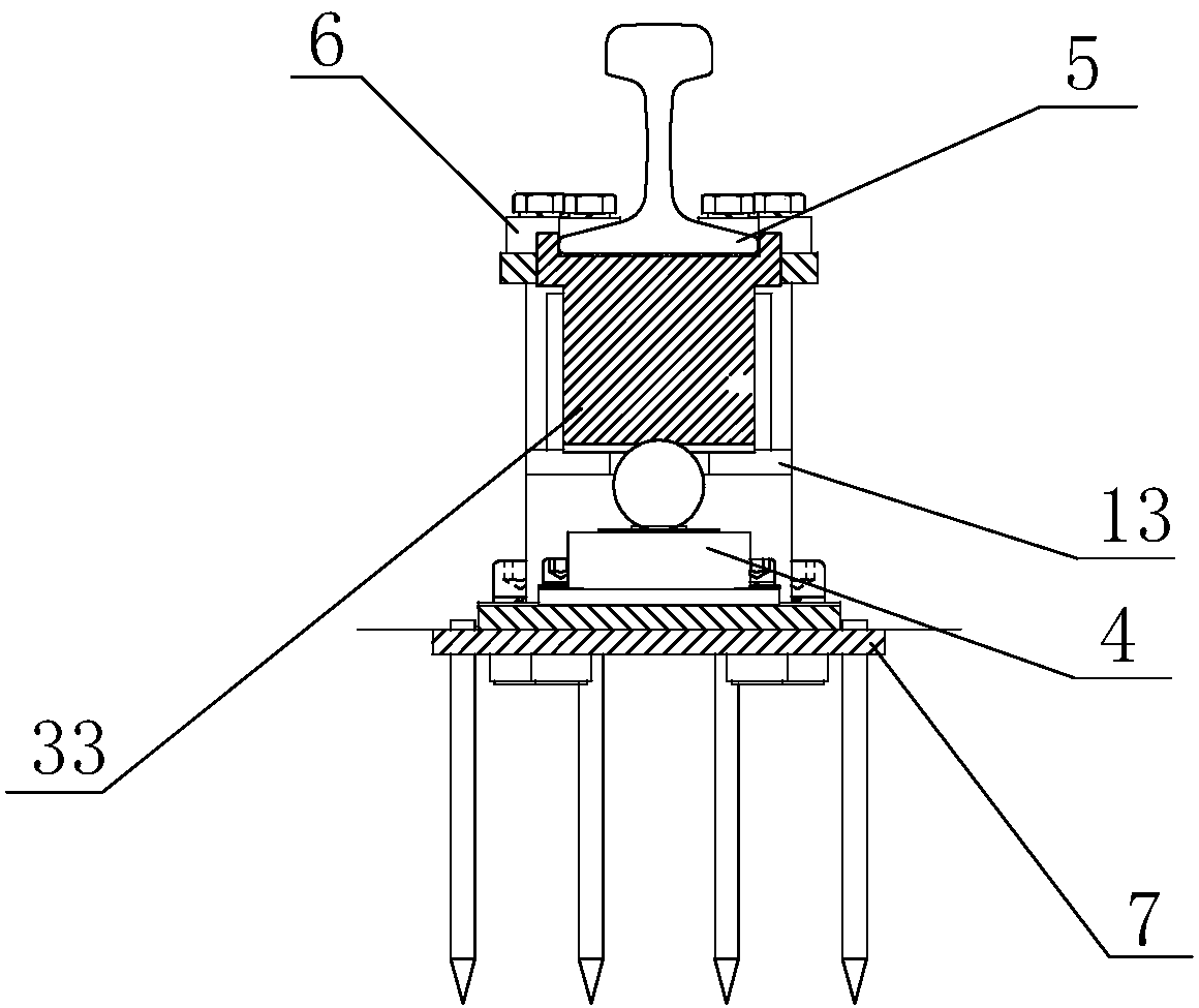
[0036] The base II1b is mainly composed of two shells 12 arranged symmetrically side by side for use as a linear rolling axis in Embodiment 1; that is, the base II1b is divided into two parts, and the two parts are arranged symmetrically side by side and are used for As the housing 12 of the linear scrolling shaft (the same as the housing part of the linear scrolling shaft in Embodiment 1); the base II1b is also provided with a mounting seat for a spoke pressure sensor, which is located below the housing 12 of the linear scrolling shaft and connected to the linear scrolling shaft The sh...
Embodiment 3
[0038] Embodiment 3: A measuring mechanism unit of a rolling stock weighing platform
[0039] The rolling stock weighing platform measuring mechanism unit is used to detect the weight of each wheel of the rolling stock, and is mainly composed of two end load bearing mechanisms installed longitudinally and a weighing rail 5. The end load bearing mechanism is the one described in Embodiment 1. The end bearing mechanism described above, the two ends of the weighing rail are respectively fixed on the grooves 31 of the corresponding bearing columns of the two end bearing mechanisms; the transition rail installation mechanism 11 of the end bearing mechanism is equipped with transition rail. The following is the specific structure of a rolling stock weighing platform measuring mechanism unit of the present embodiment 3:
[0040] The rolling stock weighing platform measuring mechanism unit is mainly composed of two end bearing mechanisms installed longitudinally and a weighing rail, ...
PUM
 Abstract
Description
Claims
Application Information
 - R&D Engineer
- R&D Manager
- IP Professional
- Industry Leading Data Capabilities
- Powerful AI technology
- Patent DNA Extraction
Browse by: Latest US Patents, China's latest patents, Technical Efficacy Thesaurus, Application Domain, Technology Topic, Popular Technical Reports.
© 2024 PatSnap. All rights reserved.Legal|Privacy policy|Modern Slavery Act Transparency Statement|Sitemap|About US| Contact US: help@patsnap.com


