Cleaning structure for flat mop and cleaning tool thereof

A flat mop and cleaning structure technology, applied in the field of cleaning appliances, can solve the problems of increased material cost and transportation cost, increased volume of cleaning tools, unclean mop, etc., and achieves wide wiping range, durable structure, and convenient water injection operation. Effect

Pending Publication Date: 2018-09-14
黄宸宇
View PDF6 Cites 6 Cited by
  • Summary
  • Abstract
  • Description
  • Claims
  • Application Information

AI Technical Summary

Problems solved by technology

However, such a structure is provided with a cleaning bucket and a dehydration bucket respectively, which increases the volume of the cleaning tool, increases the cost of materials and transportation costs, and also repeatedly installs two mouth stroke extrusion devices; or a working area is set in the cleaning bucket, and A control valve is provided between the working area and the cleaning bucket to control the cleaning bucket to inject water into the working area. This structure saves space, but the water in the cleaning bucket is mixed with the sewage or dirt discharged from the mouth-stripping extrusion device. , and then enter the work area, so that the flat mop is cleaned in sewage except for the first time in clean water, and then wiped, making the mop not clean. If the water is changed frequently, it will cause the cleaning water waste

Method used


Image

  • Cleaning structure for flat mop and cleaning tool thereof
  • Cleaning structure for flat mop and cleaning tool thereof
  • Cleaning structure for flat mop and cleaning tool thereof

Examples


Embodiment 1

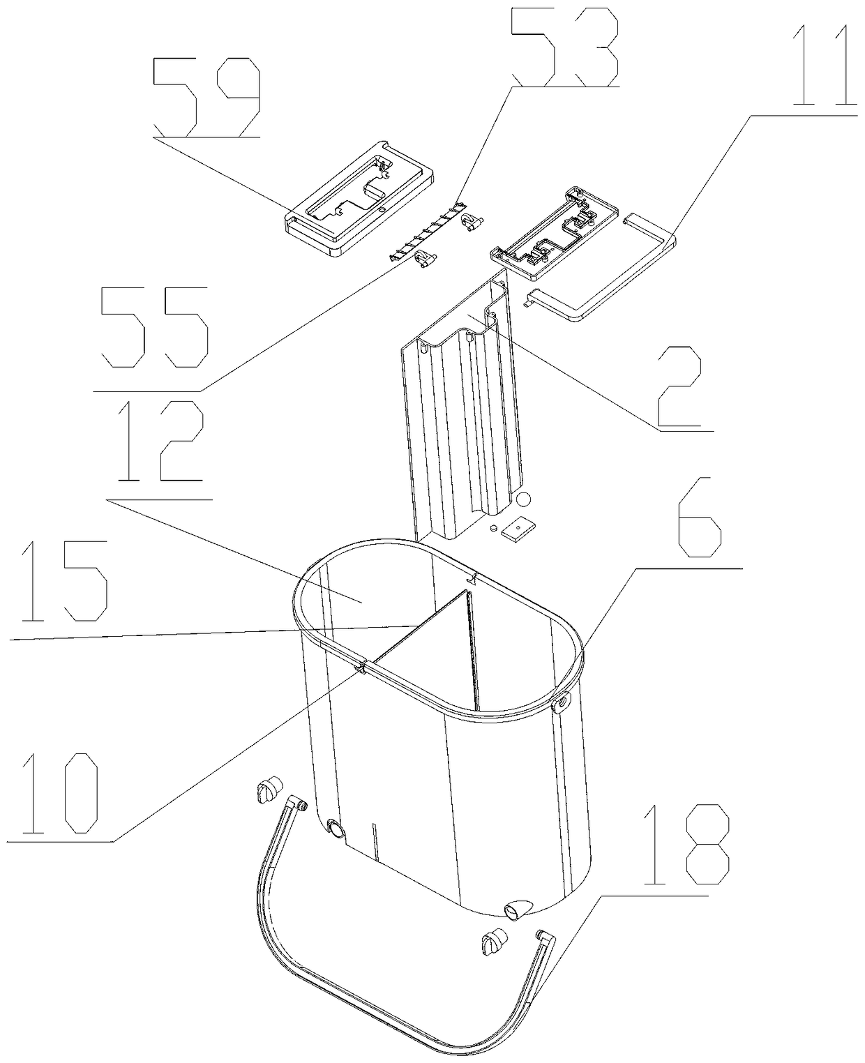
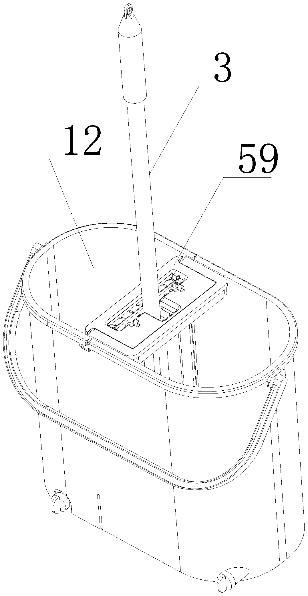
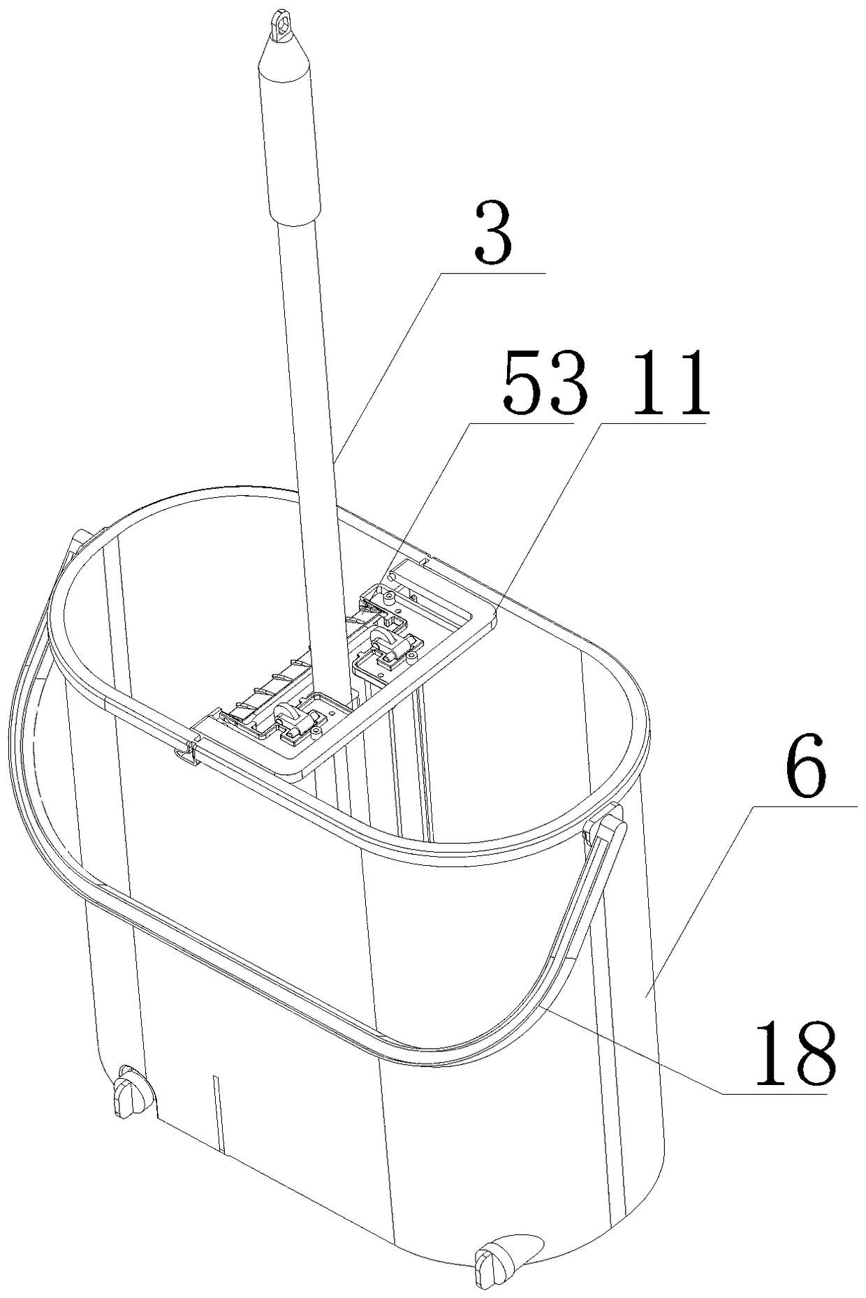
[0067] Such as Figure 1 to Figure 12 Shown, a kind of flat mop cleaning structure of the present invention comprises:

[0068] The working chamber includes a side wall 1 and an installation opening 2 surrounded by the side wall;

[0069] The scraping part 5 is detachably connected to the installation port 2, and the flat mop 3 extends into the working chamber through the scraping part for cleaning, and the scraping part 5 scrapes and presses the flat mop 3 to realize the decontamination of the flat mop 3 and dehydration;

[0070] There is also a housing 6 for containing cleaning water and passing the cleaning water into the working chamber;

[0071] The scraping part 5 is equipped with a sewage channel 4, and the sewage channel 4 cooperates with the scraping part 5 to discharge the sewage or dirt squeezed out by the cleaning mop;

[0072] The working chamber extends into the housing 6 and is detachably installed on the installation port 2. The working chamber is provided wit...


PUM


Abstract

The invention discloses a cleaning structure for a flat mop and a cleaning tool thereof. The cleaning structure comprises a working chamber comprising a side wall and a mounting opening defined by theside wall; a scraping member detachably connected to the mounting opening, wherein the flat mop stretches into the working chamber for cleaning through the scraping member, the scraping member scrapes and presses the flat mop to achieve decontamination and dehydration of the flat mop; a casing for accommodating cleaning water and introducing the cleaning water into the working chamber. The scraping member is provided with a sewage channel. The sewage channel is matched with the scraping member to discharge sewage or dirt squeezed by the cleaning mop. The working chamber is detachably installed in the casing, and the working chamber is provided with a water inlet for introducing the cleaning water into the casing, and the water inlet is equipped with a sealing part for sealing the water inlet. A latch is arranged on the working chamber or the scraping member, a clamping groove is formed in the casing at the matched position, the clamping groove comprises a pressing part and a clampingpart, and the latch is clamped in the clamping part through the pressing part to press the water inlet and the sealing part and prevent the cleaning water from entering the working chamber.

Description

technical field [0001] The invention relates to a cleaning appliance, in particular to a cleaning structure and a cleaning tool for a flat mop. Background technique [0002] The cleaning tool structures of current various flat mops are numerous. Such as comprising a mop and a cleaning bucket, the lower end of the mop is connected to a flat cleaning head, the cleaning bucket includes a cleaning bucket and a dehydration bucket, and both the cleaning bucket and the dehydration bucket are provided with a mouth-stroke extrusion device at the mouth, and the mouth of the cleaning bucket is squeezed during cleaning. The pressing device moves up and down to realize cleaning and squeezing, and the dehydration bucket is dehydrated. However, such a structure is provided with a cleaning bucket and a dehydration bucket respectively, which increases the volume of the cleaning tool, increases the cost of materials and transportation costs, and also repeatedly installs two mouth stroke extr...

Claims


Application Information

Patent Timeline
Patent Type & Authority Applications(China)
IPC IPC(8): A47L13/58
CPCA47L13/58
Inventor 黄宸宇黄建峰高峰
Owner 黄宸宇
Why Eureka
Try Eureka